
Image signal processing apparatus, imaging apparatus, image signal processing method and computer program thereof

Inactive Publication Date: 2007-07-05
SONY CORP
View PDF25 Cites 26 Cited by
  • Summary
  • Abstract
  • Description
  • Claims
  • Application Information

AI Technical Summary

Benefits of technology

[0020] The present invention is contemplated to provide an image signal processing apparatus, an imaging apparatus, an image signal processing method and a computer program thereof, capable of producing a high-quality image data with reduced noise even for such images to be captured with a single-plate color solid-state imager under an insufficient illumination such as in the darkness, in a low illumination condition with its light source containing much of an infrared light, or in a low illumination using an auxiliary light of infrared.

Problems solved by technology

An improvement of image quality of images captured with a digital still camera or a movie camera in a low illumination condition has become an important issue.
In this case, decreased shutter speed results in a camera shake and image blurring.
Also, as to the aperture value of lens, there is normally a limit; therefore it is difficult to make it brighter than a certain limit.
Further, when an external visible light source is used, there is a problem that an illumination environment of scene or feel of ambient illumination is degraded by flash.
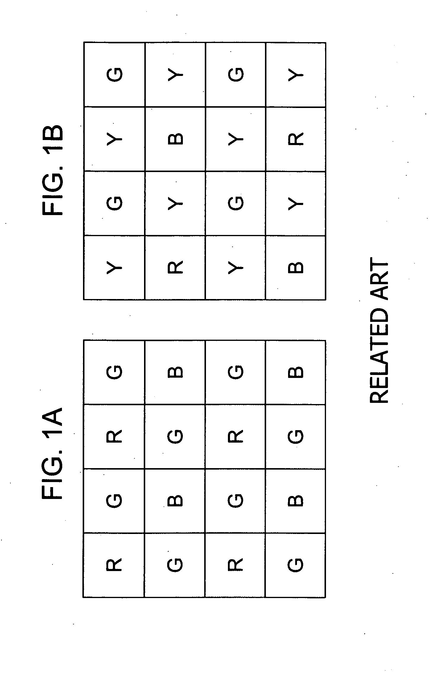
Such color arrays as shown in FIG. 1B may be effective if a sufficient lighting is provided, however, when a sufficient lighting is not provided such as in darkness, or in a low illumination condition although its light source contains much of infrared light, or in a capturing condition with a low illumination with an auxiliary light source of infrared being used, there remains a problem that sensitivity is still insufficient thereby prohibiting to produce a high quality image with reduced noise.

Method used


Image

  • Image signal processing apparatus, imaging apparatus, image signal processing method and computer program thereof
  • Image signal processing apparatus, imaging apparatus, image signal processing method and computer program thereof
  • Image signal processing apparatus, imaging apparatus, image signal processing method and computer program thereof

Examples


Embodiment Construction

[0056] By referring to the accompanying drawings, an image signal processing apparatus, an imaging apparatus, an image signal processing method and a computer program thereof according to the present invention will be described more in detail in the sequential order as follows. [0057] 1. Configuration of Imager [0058] 2. First image signal processing example [0059] 3. Second image signal processing example

[1. Configuration of Imager]

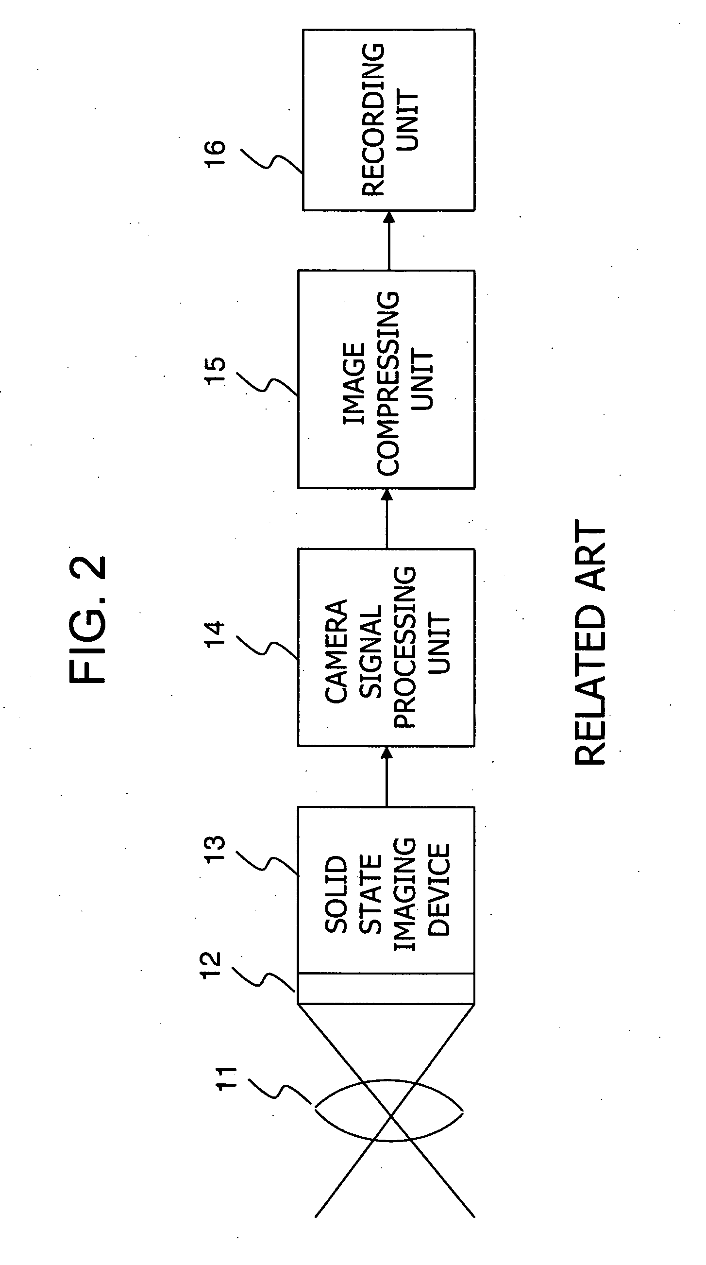
[0060] First, a description will be given to the configuration of an imaging device (hereinafter, referred to as imager) applied to an imaging apparatus of the present invention. The imaging apparatus of the present invention has a configuration that is basically similar to the one described above with reference to FIG. 2, but the imager applied to the imaging apparatus has a configuration different from the Bayer color array described with reference to FIG. 1. The configuration of the imager applied to the imaging apparatus of the present invention is...


PUM


Abstract

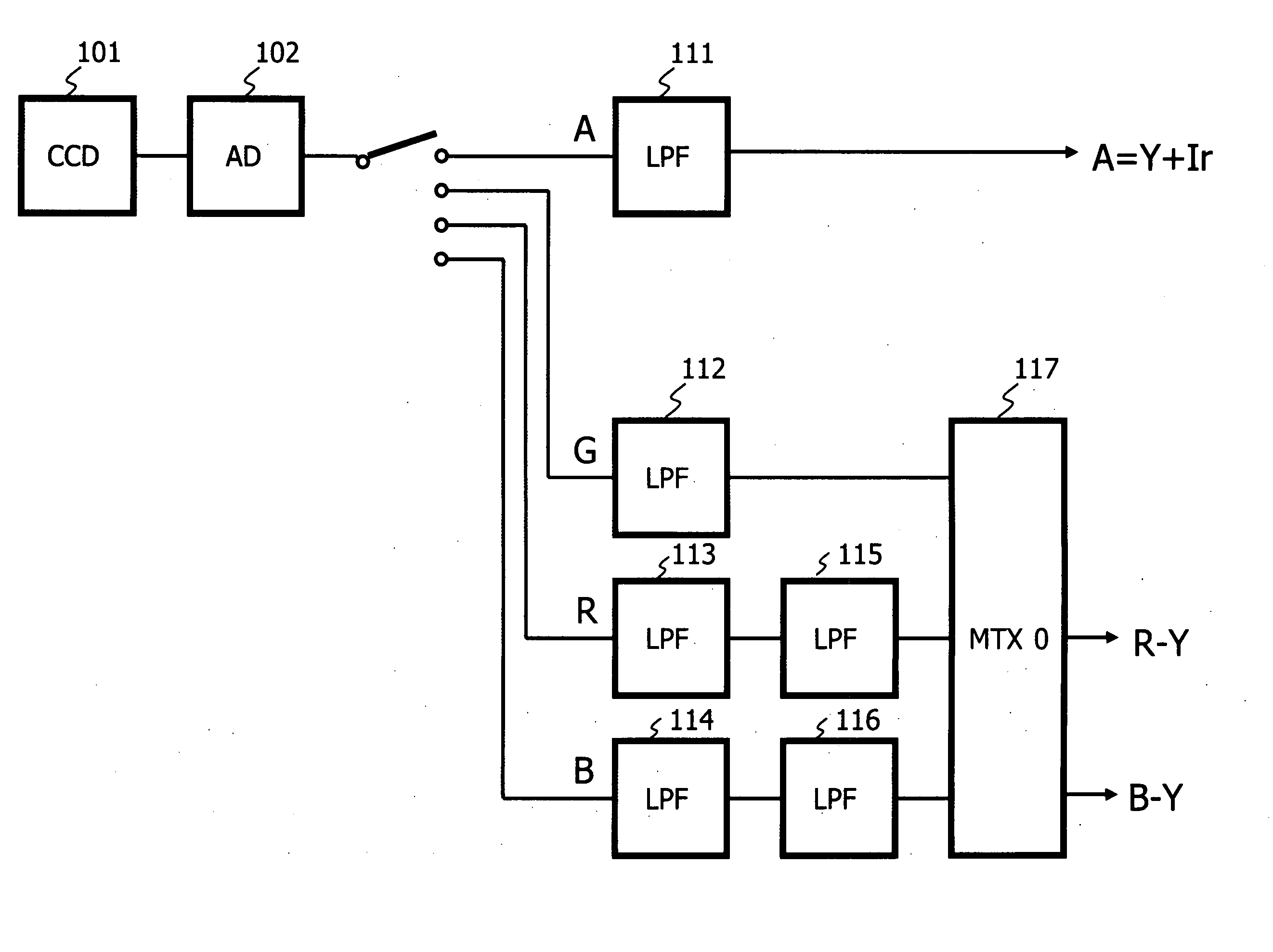
There is provided an image signal processing apparatus having a luminance signal producing unit which receives input of a mosaic image of a signal acquired by a wide wavelength range signal acquisition element from signals acquired by a single-plate imaging device having element arrays including a specific wavelength range signal acquisition element for acquiring a visible light signal corresponding to a specific light wavelength range and the wide wavelength range signal acquisition element for acquiring a light signal containing a visible light component and an invisible light component, and produces, as a luminance signal, a wide wavelength range signal demosaic image; and a color difference signal producing unit which receives input of a mosaic image of a signal acquired by the specific wavelength range signal acquisition element, produces a visible light range signal demosaic image, and produces a color difference signal based on the visible light range signal demosaic image.

Description

BACKGROUND OF THE INVENTION [0001] 1. Field of the Invention [0002] The present invention relates to an image signal processing apparatus, an imaging apparatus, an image signal processing method and a computer program, and more particularly to an image signal processing apparatus, an imaging apparatus, an image signal processing method and a computer program for performing signal processing of imaged data by a solid state imaging device of a single plate color system. [0003] 2. Description of Related Art [0004] A general solid state imaging device of the single plate color system has a color filter stuck thereto to transmit a specific wavelength component in each pixel to a surface of an imaging device, and restores necessary color components by a set of a plurality of pixels. At this time, for example, a color array expressing red (R), green (G) and blue (B) by a set of four pixels as shown in FIG. 1A or an array in which white (Y) as a luminance signal is combined with red (R), gr...

Claims


Application Information

Patent Timeline
IPC IPC(8): H04N9/68
CPCH04N5/332H04N2209/047H04N9/045H04N23/11H04N25/131H04N25/133H04N25/135H04N23/843
Inventor OHKI, MITSUHARUMITSUNAGA, TOMOOYOSHIMURA, SHINICHIKASAI, MASANORI
Owner SONY CORP
Learn More