Check patentability & draft patents in minutes with Patsnap Eureka AI!

Video encoding method and apparatus and video decoding method and apparatus

a video encoding and video technology, applied in the field of video en video decoding methods and apparatuses, can solve the problems of increasing the total code amount, and affecting the accuracy of the prediction

Inactive Publication Date: 2007-07-05
KOTO SHINICHIRO +2
View PDF12 Cites 21 Cited by
  • Summary
  • Abstract
  • Description
  • Claims
  • Application Information

AI Technical Summary

Benefits of technology

This approach enhances prediction efficiency and reduces encoding and decoding costs by optimizing the encoding of fading pictures, leading to improved picture quality and lower overhead in encoded data.

Problems solved by technology

With regard to temporal enlargement / reduction and rotation of pictures or temporal variations in signal amplitude such as fade-in and fade-out, however, high prediction efficiency cannot always be obtained.
In encoding at a constant bit rate, if such pictures from which high prediction efficiency cannot be obtained are input, a great deterioration in picture quality may occur.
In encoding at a variable bit rate, a large code amount is consumed for pictures with poor prediction efficiency to suppress deterioration in picture quality, resulting in an increase in total code amount.
This requires an enormous amount of transformation computation.
This leads to an enormous amount of encoding computation or an enormous increase in hardware cost and the like.
In addition, a transformation parameter itself must be encoded as well as a prediction residual error, and hence the encoded data becomes enormous.
In addition, inverse affine transformation is required at the time of decoding, resulting in a great amount of decoding computation or a very high hardware cost.
As described above, in the conventional video encoding methods such as MPEGs, sufficient prediction efficiency cannot be obtained with respect to temporal changes in video other than translations.
In addition, in the video encoding and decoding method using affine transformation, although prediction efficiency itself can be improved, the overhead for encoded data increases and the encoding and decoding costs greatly increase.

Method used


Image

  • Video encoding method and apparatus and video decoding method and apparatus
  • Video encoding method and apparatus and video decoding method and apparatus
  • Video encoding method and apparatus and video decoding method and apparatus

Examples


first embodiment

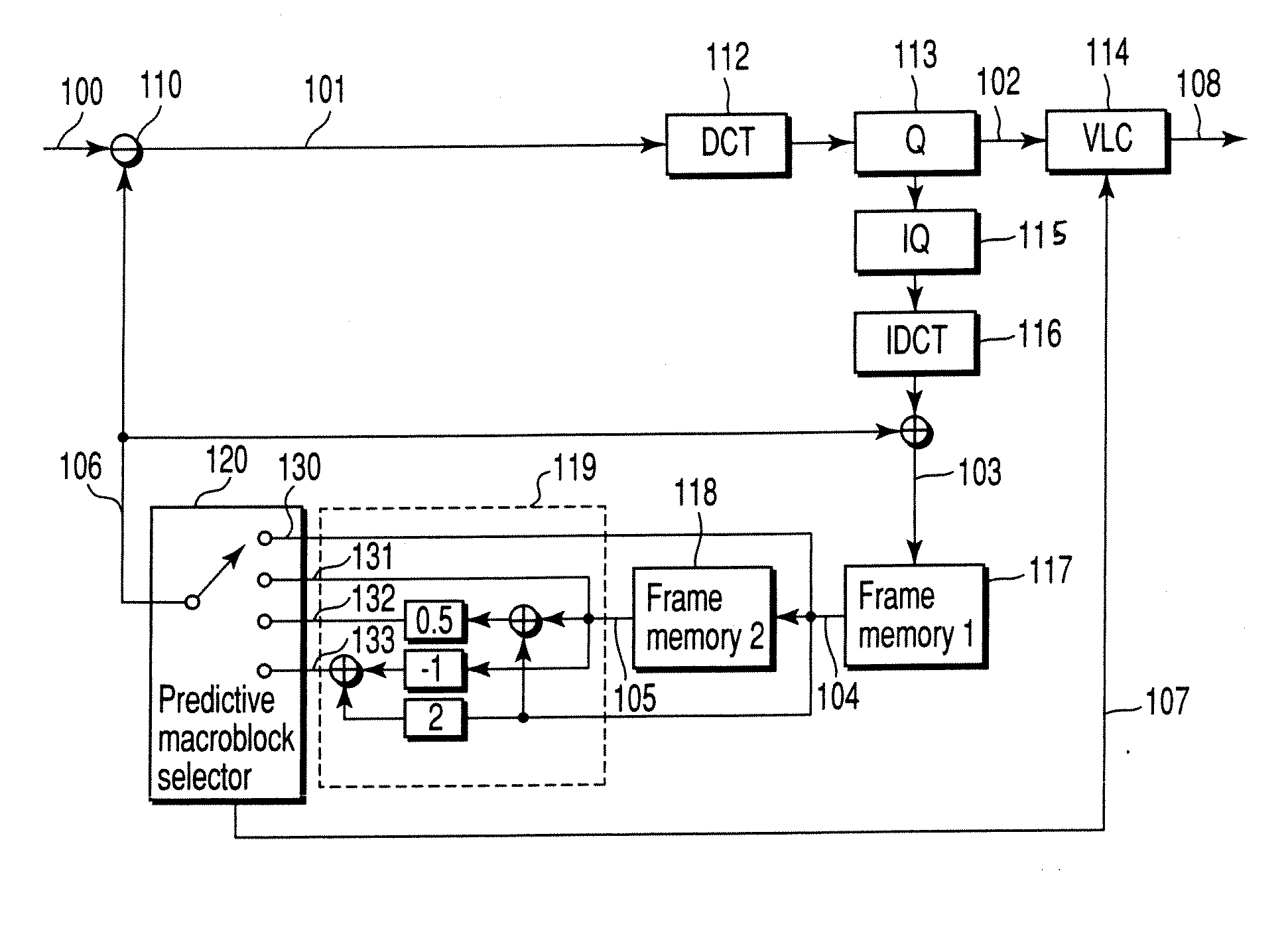
[0054]FIG. 1 shows the arrangement of a video encoding apparatus according to the first embodiment of the present invention. The video encoding apparatus shown in FIG. 1 may be implemented by hardware or software using a computer. Part of the processing performed by the apparatus may be implemented by hardware, while the remaining part may be implemented by software. This equally applies to video encoding apparatuses according to the other embodiments to be described later.

[0055] Referring to FIG. 1, a predictive macroblock generator 119 generates predictive macroblock signals 130 to 133 for a video signal (to-be-encoded frame) 100 input for every frame from the encoded frames stored in a first reference frame memory 117 and second reference frame memory 118. A predictive macroblock selector 120 selects an optimal predictive macroblock signal from the predictive macroblock signals 130 to 133, and generates a prediction picture signal 106 by using the selected predictive macroblock ...

second embodiment

[0064]FIG. 2 shows the arrangement of a video encoding apparatus according to the second embodiment of the present invention. In this embodiment, a fade detector 140 for an input video signal 100 is added to the video encoding apparatus according to the first macroblock shown in FIG. 1. The fade detector 140 calculates an average luminance signal for each frame of the input video signal 100. If a change in luminance over time has a predetermined slope, the fade detector 140 determines that the picture represented by the input video signal 100 is a fading picture, and notifies a predictive macroblock selector 120 of the determination result as a fade detection signal 141.

[0065] If the fade detector 140 determines that the picture represented by the input video signal 100 is a fading picture, the predictive macroblock selector 120 limits a prediction mode to a prediction from one reference frame or a prediction based on linear extrapolation or linear interpolation of a plurality of r...

third embodiment

[0083]FIGS. 8 and 9 show the arrangements of a video encoding apparatus and video decoding apparatus according to the third embodiment of the present invention. In the first and second embodiments, a prediction is performed on the basis of the linear sum of a maximum of two reference frames. In contrast to this, the third embodiment can perform a prediction based on selection of one specific frame for each macroblock by using three or more reference frames or the linear sum of a plurality of reference frames.

[0084] The video encoding apparatus shown in FIG. 8 includes reference frame memories 117, 118, and 152 corresponding to the maximum reference frame count (n). Likewise, the video decoding apparatus in FIG. 9 includes reference frame memories 217, 218, and 252 corresponding to the maximum reference frame count (n). In this embodiment, in a prediction based on a linear sum, each of predictive macroblock generators 151 and 251 generates a prediction picture signal by computing th...


PUM


Abstract

A video encoding method includes extracting at least one reference macroblock from each of a plurality of reference frames to generate a plurality of reference macroblocks, computing a linear sum of the reference macroblocks using weighting factors to generate a predictive macroblock, generating a motion vector between the video macroblock and the reference macroblock corresponding to the predictive macroblock, generating a prediction error signal between the predictive macroblock and the video macroblock, and encoding the prediction error signal, a first index indicating the plurality of reference frames, a second index indicating the weighting factors and the motion vector.

Description

CROSS-REFERENCE TO RELATED APPLICATIONS [0001] This application is a Division of U.S. application Ser. No. 10 / 409,068, filed Apr. 9, 2003, the entire contents of which is incorporated herein by reference. [0002] This application is based upon and claims the benefit of priority from the prior Japanese Patent Applications No. 2002-108102, filed Apr. 10, 2002; and No. 2002-341239, filed Nov. 25, 2002, the entire contents of both of which are incorporated herein by reference.BACKGROUND OF THE INVENTION [0003] 1. Field of the Invention [0004] The present invention relates to a video encoding method and apparatus and a video decoding method and apparatus which use a motion compensation predictive inter-frame encoding. [0005] 2. Description of the Related Art [0006] As video compression encoding techniques, MPEG-1 (ISO / IEC11172-2), MPEG-2 (ISO / IEC13818-2), MPEG-4 (ISO / IEC14496-2), and the like have been widely used. In these video encoding schemes, encoding is performed by a combination of...

Claims


Application Information

Patent Timeline
Patent Type & Authority Applications(United States)
IPC IPC(8): H04N11/02H04N11/04H04N19/50G06T9/00H03M7/36H04N19/105H04N19/127H04N19/132H04N19/134H04N19/137H04N19/139H04N19/157H04N19/176H04N19/196H04N19/423H04N19/503H04N19/51H04N19/513H04N19/553H04N19/59H04N19/61H04N19/625H04N19/91
CPCH04N19/105H04N19/52H04N19/176H04N19/172H04N19/46H04N19/577H04N19/132H04N19/137H04N19/142H04N19/573H04N19/61
Inventor KOTO, SHINICHIROCHUJOH, TAKESHIKIKUCHI, YOSHIHIRO
Owner KOTO SHINICHIRO
Features
  • R&D
  • Intellectual Property
  • Life Sciences
  • Materials
  • Tech Scout
  • Unparalleled Data Quality
  • Higher Quality Content
  • 60% Fewer Hallucinations
Learn More