Apparatus and method for frequency conversion

a frequency conversion and apparatus technology, applied in the field of apparatus and method for frequency conversion, can solve the problems of increasing the cost of components, complicated circuitry, and high cost of typical frequency multiplier stages, and achieve the effects of saving cost, complexity, size, weight, and other factors

Active Publication Date: 2007-07-05
HRL LAB
View PDF7 Cites 2 Cited by
  • Summary
  • Abstract
  • Description
  • Claims
  • Application Information

AI Technical Summary

Benefits of technology

[0011] Transceivers according to embodiments of the present invention allow for the same circuitry to be used for both frequency up conversion and down conversion, resulting in significant savings in cost, complexity, size, weight, and other factors as compared to other transceivers known in the art. For example, a transceiver according to an embodiment of the present invention may use a passive frequency multiplier comprising a varactor diode. In the transceiver, the varactor diode, in combination with passive components, is disposed to provide for up conversion of a transmitted signal and down conversion of a received signal. A preferred embodiment of the present invention uses a heterojunction barrier varactor (HBV) diode in the passive frequency multiplier. Due to the use of the HBV diode, no DC bias or idler circuitry is required for the multiplier.

Problems solved by technology

As a result, all the components of the transceiver (mixers, amplifiers, etc.) must be operable at the higher multiplied frequency which increases the cost of the components.
Furthermore, typical frequency multiplier stages comprise expensive active components that require complicated circuitry and introduce undesirable noise into the system.
These components can impose considerable cost, size and power constraints on the system compared to components that need only operate at lower frequencies.
Again, such components operating in the millimeter wave frequency band may cost considerably more, be larger than, and / or require more power than components that need only operate at lower frequencies.

Method used


Image

  • Apparatus and method for frequency conversion
  • Apparatus and method for frequency conversion
  • Apparatus and method for frequency conversion

Examples


Embodiment Construction

[0017] The present invention will now be described more fully hereinafter with reference to the accompanying drawings, in which preferred embodiments of the invention are shown. This invention may be embodied in many different forms and should not be construed as limited to the embodiments set forth herein. Further, the dimensions of certain elements shown in the accompanying drawings may be exaggerated to more clearly show details. The present invention should not be construed as being limited to the dimensional relations shown in the drawings, nor should the individual elements shown in the drawings be construed to be limited to the dimensions shown.

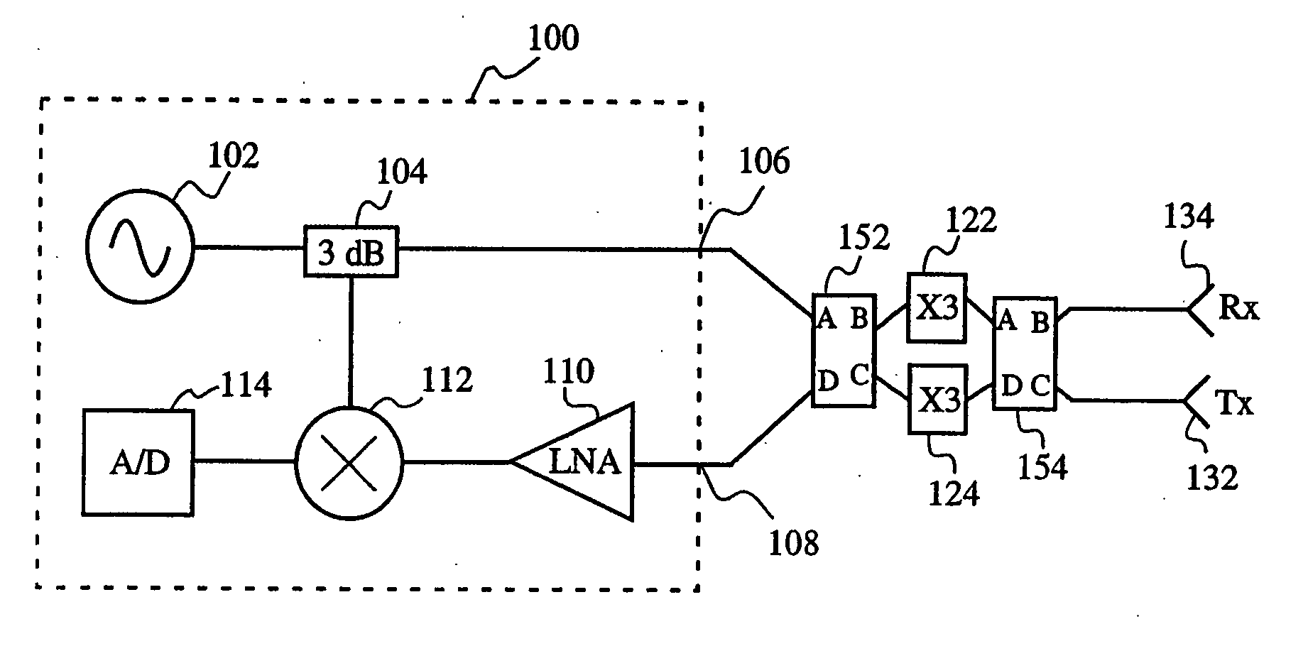
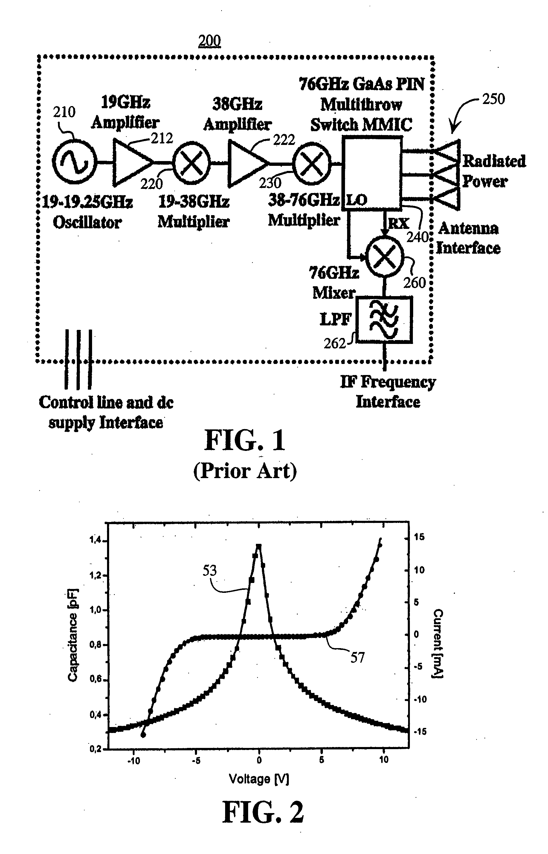
[0018] As shown in FIG. 1, up conversion from a microwave frequency signal to a millimeter wave frequency signal may be accomplished by using a series of frequency doublers. Up conversion from a microwave frequency signal (or from a lower frequency millimeter wave signal) to a higher frequency millimeter wave signal may also be accomp...


PUM


Abstract

An apparatus for frequency up conversion and down conversion using frequency multiplier circuits. The frequency multiplier circuits receive a lower frequency signal and are operated in a forward direction to provide a higher frequency output. The same frequency multiplier circuits are operated in a reverse direction by receiving a higher frequency signal and producing a lower frequency output. The frequency multiplier circuits preferably use heterojunction barrier varactor diodes to eliminate the need for DC bias or idler circuitry.

Description

BACKGROUND [0001] 1. Field [0002] The present invention relates to translating lower frequency signals to higher frequency signals and higher frequency signals to lower frequency signals. More specifically, the present invention relates to an apparatus and method for up converting microwave signals to millimeter wave signals and down converting millimeter wave signals to microwave signals for use in such applications as a radar transceiver. [0003] 2. Description of Related Art [0004] Communication and radar systems operating with signals in the microwave frequency band (3-30 GHz) are well-known in the art. Systems operating at higher frequencies are also known in the art. Such systems are often implemented using one or more transceivers that both transmit and receive the signals. Operating at higher frequencies is desirable because the size of the antennas used with the transceiver scale inversely with the operational frequency. As a result, higher frequencies result in smaller ante...

Claims


Application Information

Patent Timeline
Patent Type & Authority Applications(United States)
IPC IPC(8): H04B1/38
CPCH03D7/00
Inventor LYNCH, JONATHAN J.
Owner HRL LAB
Why Eureka
Try Eureka