Apparatus and method for molding onto a stretched blank

a technology of elastic blanks and molding apparatus, which is applied in the direction of turning machine accessories, drawing profiling tools, buttons, etc., can solve the problems of complex manufacturing process, relatively high apparatus cost, and the desire to have a loaded fabric, so as to save cost, complexity and floor space, and achieve simple and effective

Active Publication Date: 2007-05-24
ILLINOIS TOOL WORKS INC
View PDF15 Cites 6 Cited by
  • Summary
  • Abstract
  • Description
  • Claims
  • Application Information

AI Technical Summary

Benefits of technology

[0013] The present invention provides a relatively simple and effective apparatus and method for molding a component onto a loaded (or stretched) elastic blank. Because the stretching system is integrated into the mold, the loom of prior systems is eliminated saving in cost, complexity and floor space. Integration of the stretching system into the mold also reduces the time between stretching of the blank and molding of the component. This reduces, and possibly eliminates, decay in the blank. Further, the apparatus of the present invention yields less waste material because the amount of peripheral material necessary during the manufacturing process is reduced. The shot pins of the placing tool provide a relatively simple and effective mechanism for transferring the blank into the stretching assembly. The air knife assembly facilitates proper clamping of the blank by straightening out any curling in the fabric. The stretch measuring tool provides a simple and effective mechanism that can be used periodically to test for proper stretching of the fabric. The stretch measuring tool is integrated into the end-of-arm tooling so that it is readily activated when a test measurement is desired.

Problems solved by technology

The desire to have a loaded fabric complicates the manufacturing process—at least with respect to the process of molding the mounting component onto the fabric.
Although effective, this process and the associated apparatus suffer from various disadvantages.
For example, the apparatus is relatively expensive because it requires a stretching machine, a loom and a mold that are specially configured to interact with one another.
Also, this process results a relatively large amount of waste fabric, which can be a significant problem because of the high cost of high tech fabrics.
Further, once the fabric is stretched, it begins to decay at the locations where it is attached to the stretching machine or loom due to the focused stress.
This apparatus also requires a relatively large amount of floor space to accommodate the separate stretching machine, loom machine and mold.
Additionally, the apparatus presents quality control concerns.
Once the loom is closed on the fabric, the system no longer knows anything about the state or condition of the fabric.
This can present problems because the fabric is under a significant load and may partially separate from the loom in one location or another.
Any separation or other defects that arise after the loom is installed will go unnoticed by the system.
This may result in defective parts.
This process requires a specific amount of stretch to be built into the mold and does not provide the ability to adjust the stretch.
Although providing some benefits, these alternative methods continue to suffer from a variety of problems ranging from high cost to product quality issues.

Method used


Image

  • Apparatus and method for molding onto a stretched blank
  • Apparatus and method for molding onto a stretched blank
  • Apparatus and method for molding onto a stretched blank

Examples


Embodiment Construction

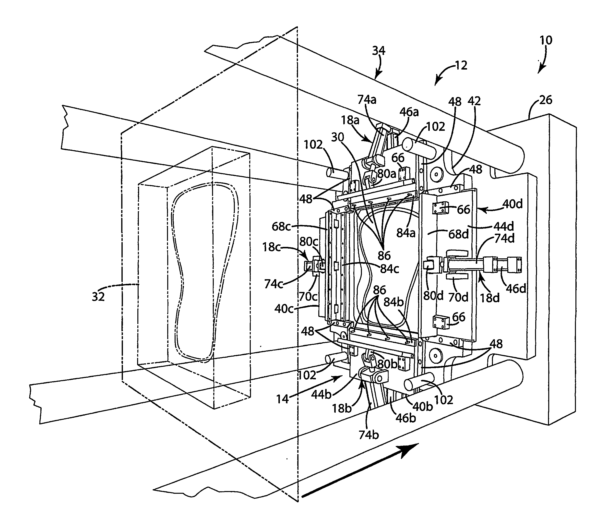
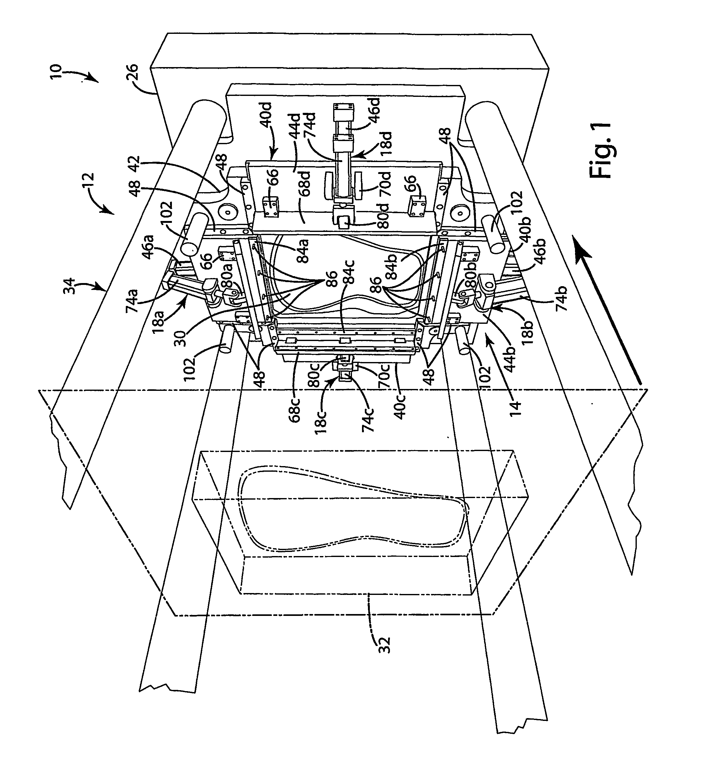
[0039] A molding apparatus in accordance with an embodiment of the present invention is shown in FIG. 1 and generally designated 10. The molding apparatus 10 generally includes a mold 12 for molding a mounting component 20 (see FIG. 16) to a load bearing fabric 16 and a stretching assembly 14 mounted adjacent the mold 12 for stretching the load bearing fabric 16 and holding it in the stretched position during molding. The stretching assembly 14 of the illustrated embodiment generally includes a plurality of clamp assemblies 18 (such as, 18a-18d) that are operable to grip the peripheral edge of the fabric 16. The clamp assemblies 18 are movable after gripping to apply the desired degree of stretch to the fabric 16. The mold 12 is adapted to be closed over the stretched fabric 16 so that the mounting component 20 can be molded onto the fabric 16 while the fabric is held in the stretched condition by the stretching assembly 14. In this embodiment, the molding apparatus 10 also includes...


PUM

PropertyMeasurementUnit
timeaaaaaaaaaa
forceaaaaaaaaaa
movementaaaaaaaaaa

Abstract

An apparatus and method for molding a component onto a stretched blank. The apparatus includes a stretching assembly mounted adjacent to a first mold part. The stretching assembly includes a plurality of clamp assemblies that grasp the peripheral edge of the blank and a plurality of slide assemblies that move the clamp assemblies away from one another to apply a stretch to the fabric. The apparatus further includes a press for closing a second mold part onto the first mold part while the fabric is held in a stretched condition by the stretching assembly. In one embodiment, the stretching assembly may include a float plate that is movable with respect to the first mold part between a stretch position and a mold position. The apparatus may include a robot with tooling for moving the fabric onto the stretching assembly. The tooling may include a plurality of shot pins that push the fabric off of the tooling onto corresponding fabric pins in the stretching machine. In one embodiment, the apparatus include a stretch measuring device adapted to measure the stretch applied to the fabric.

Description

RELATED APPLICATION [0001] This application claims the benefit of U.S. Provisional Application No. 60 / 517,274, filed Nov. 4, 2003.BACKGROUND OF THE INVENTION [0002] The present invention relates to molding apparatus and methods, and more particularly to apparatus and methods for molding onto a loaded, elastic blank. [0003] The development of high tech fabrics has permitted the incorporation of fabric into a wide variety of applications not previously consider appropriate for fabrics. For example, certain high tech fabrics have been developed that include a weave of multifilament yarns and elastomeric monofilaments. These fabrics provide remarkable load bearing characteristics, while at the same time providing appropriate elasticity to be comfortable as a load bearing fabric in seating applications. More specifically, these fabrics are now widely used to form the seats and backs of office chairs and other seating structures To enable attachment of the fabric to a chair seat or other ...

Claims


Application Information

Patent Timeline
Patent Type & Authority Applications(United States)
IPC IPC(8): B29C31/04B29C31/08B29C70/76B29CB29C31/00
CPCB29C31/008B29C70/56
Inventor SAYERS, RANDY J.TREMBLAY, PIERREWASHBURN, KELLY E.LONGSTREET, KENNETH A.
Owner ILLINOIS TOOL WORKS INC
Why Eureka
Try Eureka