
Memory bus interface

Active Publication Date: 2006-09-05
SK HYNIX INC
View PDF9 Cites 1 Cited by
  • Summary
  • Abstract
  • Description
  • Claims
  • Application Information

AI Technical Summary

Benefits of technology

[0006]Such an interface allows for a simple, direct communication path between a host bus, such as a bus system, and a target bus, such as an LPC bus. The interface consolidates several tasks into one general purpose interface, providing savings in components used, design complexity, and overall cost of implementation. Further, the length of time required for communications between different busses is substantially reduced.

Problems solved by technology

Since its speed is limited to 33 MHz, it is not designed for heavy-duty data transfer.
The LPC bus, however, is not readily compatible with other bus architectures, such as register-based memory buses, because of the discrepancy in the bus speeds.
As a result, communication between a system bus and an LPC bus cannot be achieved by a simple interface.
In the past, communication between devices that use the system bus and devices that use the LPC bus was indirect and required a significant firmware / software undertaking.
This undertaking proved to require a substantially lengthy processing time.

Method used


Image

  • Memory bus interface
  • Memory bus interface
  • Memory bus interface

Examples


Embodiment Construction

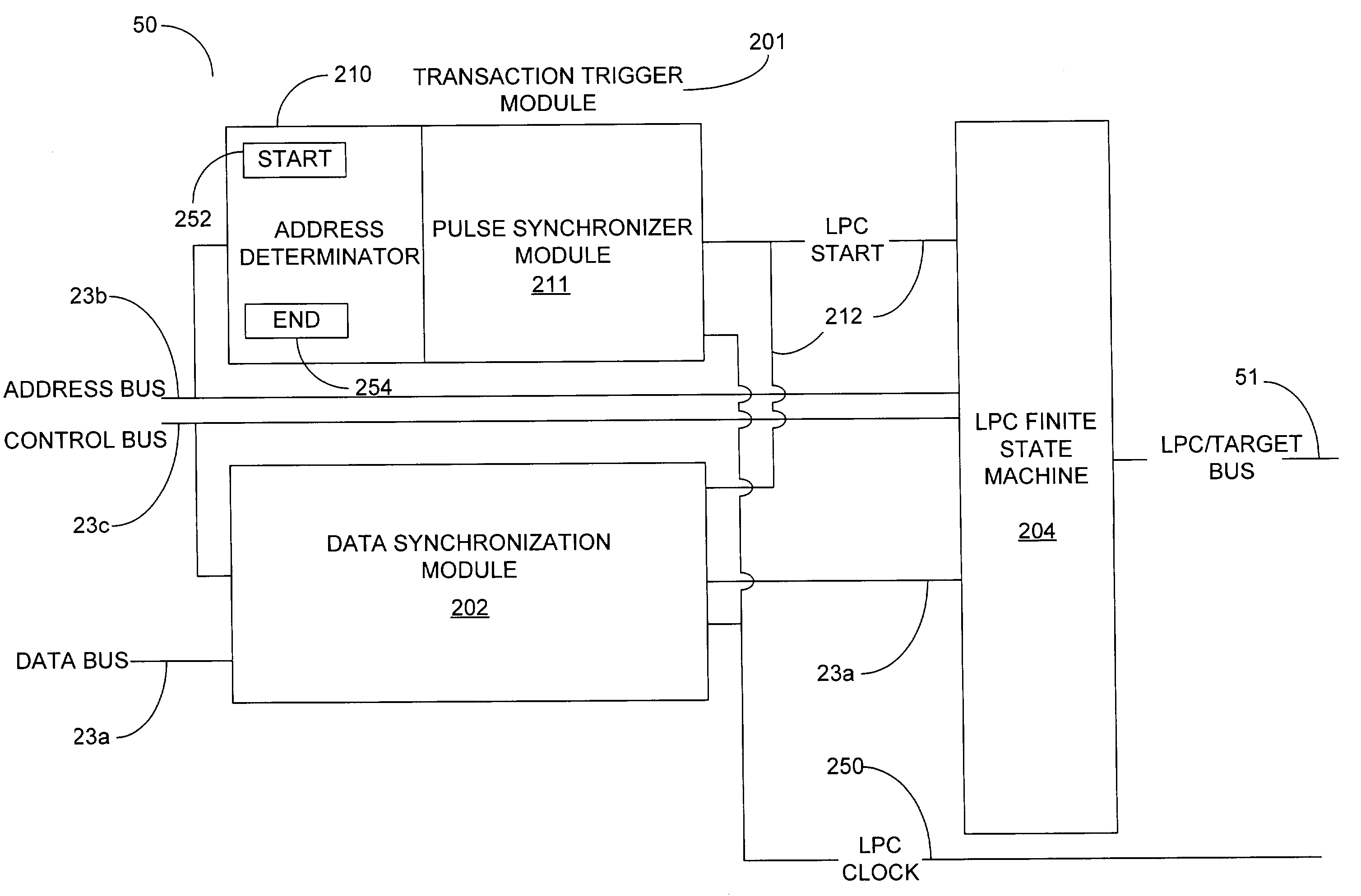
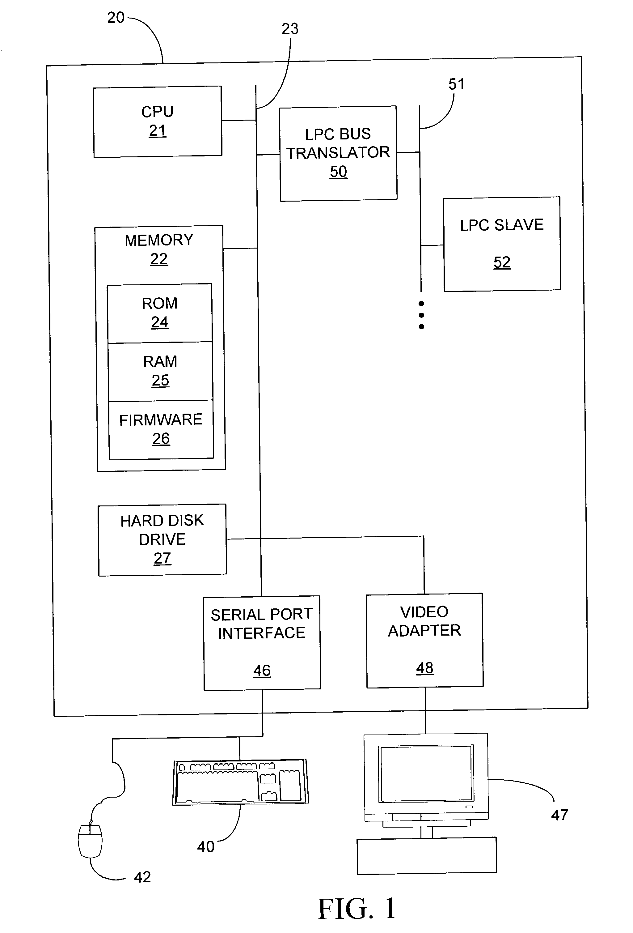
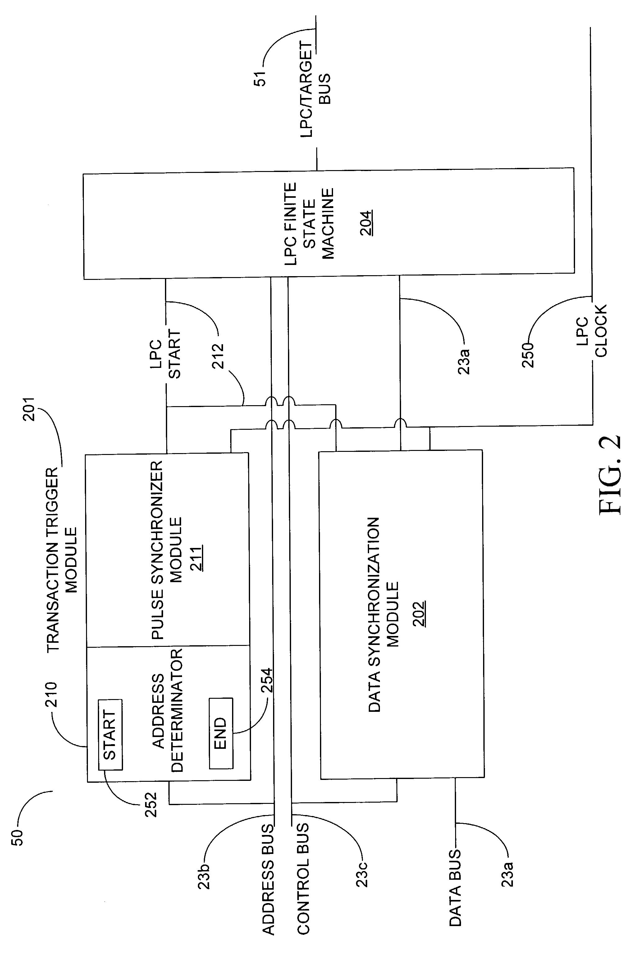
[0010]Various embodiments of the present invention are directed to a device, system, method, and computer-readable medium for facilitating data communication between two different computer bus architectures. In one embodiment, communication between a register-based memory bus and an LPC bus is achieved. FIG. 1 and the following discussion are intended to provide a brief, general description of a suitable computing environment in which the embodiments of the invention may be implemented. Those skilled in the art will appreciate that the invention may be practiced with other computer system configurations, such as, for example, hand-held devices, networked PCs, minicomputers, mainframe computers, multiprocessor systems, microprocessor-based or programmable embedded computers, the like. The invention may also be practiced in distributed computing environments where tasks are performed by remote processing devices that are linked through a communication network.

[0011]FIG. 1 is a block d...


PUM


Abstract

An interface allows communication between a host device coupled to a host bus and a target device coupled to a target bus. First, the interface receives the address of the target device from the host device via the host bus, where the address has a first width. Next, the interface converts the received address from the first width into one or more address components each having a second width. Then, the circuit accesses the target device by driving the one or more address components onto the target bus. Such an interface allows for a simple, direct communication path between the host bus, such as a system bus, and a target bus, such as an LPC bus. The interface consolidates several tasks into one general purpose interface, providing savings in components used, design complexity, and overall cost of implementation. Further, the length of time required for communications between interfaced busses is substantially reduced.

Description

BACKGROUND OF THE INVENTION[0001]A Low-Pin Count (LPC) bus is an internal-communication bus for computer systems and has been implemented in recent years to gradually replace the Industry Standard Architecture (ISA) bus. For example, the LPC Interface Specification 1.0 available from Intel Corporation of Santa Clara, Calif. calls for an LPC interface between a computer system's core logic chipset and motherboard I / O functions.[0002]The LPC bus architecture is a serial, 7-pin simple bus with a 33 MHz clock. There are no defined slots, unlike the ISA and PCI buses, thus only on-board solutions are used in the LPC architecture. Since its speed is limited to 33 MHz, it is not designed for heavy-duty data transfer. Devices that are likely to be found on the LPC bus are legacy devices, such as Super I / Os, and flash boot devices. The LPC bus architecture is software transparent to higher level I / O functions and is compatible with existing peripheral devices and applications. The LPC bus, h...

Claims


Application Information

Patent Timeline
IPC IPC(8): G06F13/40G06F7/38G06F13/36G06F12/10
CPCG06F13/404G06F13/4018G06F12/10
Inventor CHHEDA, SACHIN
Owner SK HYNIX INC
Learn More