Puncture device

a puncture device and tip technology, applied in the field of puncture devices, can solve the problems of inability to efficiently absorb medical agents, difficulty in inserting the tip portion of the puncture device,

Inactive Publication Date: 2007-07-05
TERUMO KK
View PDF23 Cites 68 Cited by
  • Summary
  • Abstract
  • Description
  • Claims
  • Application Information

AI Technical Summary

Benefits of technology

[0045] According to the present invention, it is possible for a puncture needle to reach a predetermined region certainly after being stuck from a skin. Also, it is possible for an indwelling device to be indwelled in a predetermined region certainly.

Problems solved by technology

Accordingly, it is difficult to insert a tip portion of the puncture device, for example, a needlepoint of the puncture needle accurately to the dermis which exists between the epidermis and the subcutis and if the needlepoint is inserted erroneously to the subcutis or the like, there occurs a problem such that a medical agent cannot be absorbed efficiently.

Method used


Image

  • Puncture device
  • Puncture device
  • Puncture device

Examples


first exemplified embodiment

[0059] First, it will be explained with respect to a first exemplified embodiment of a puncture device 1 of the present invention.

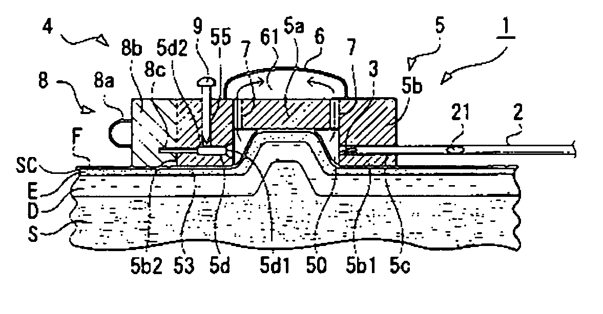
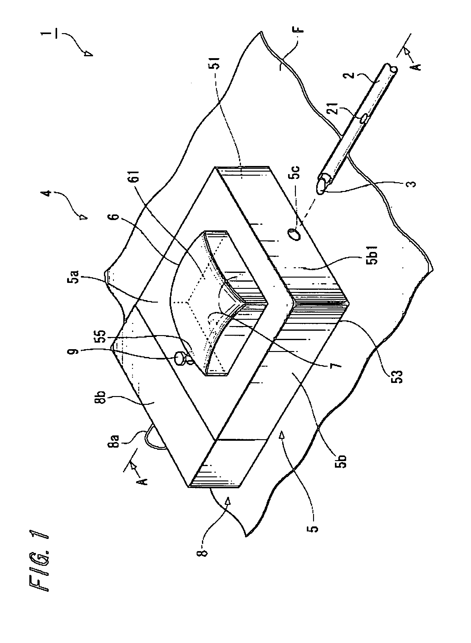
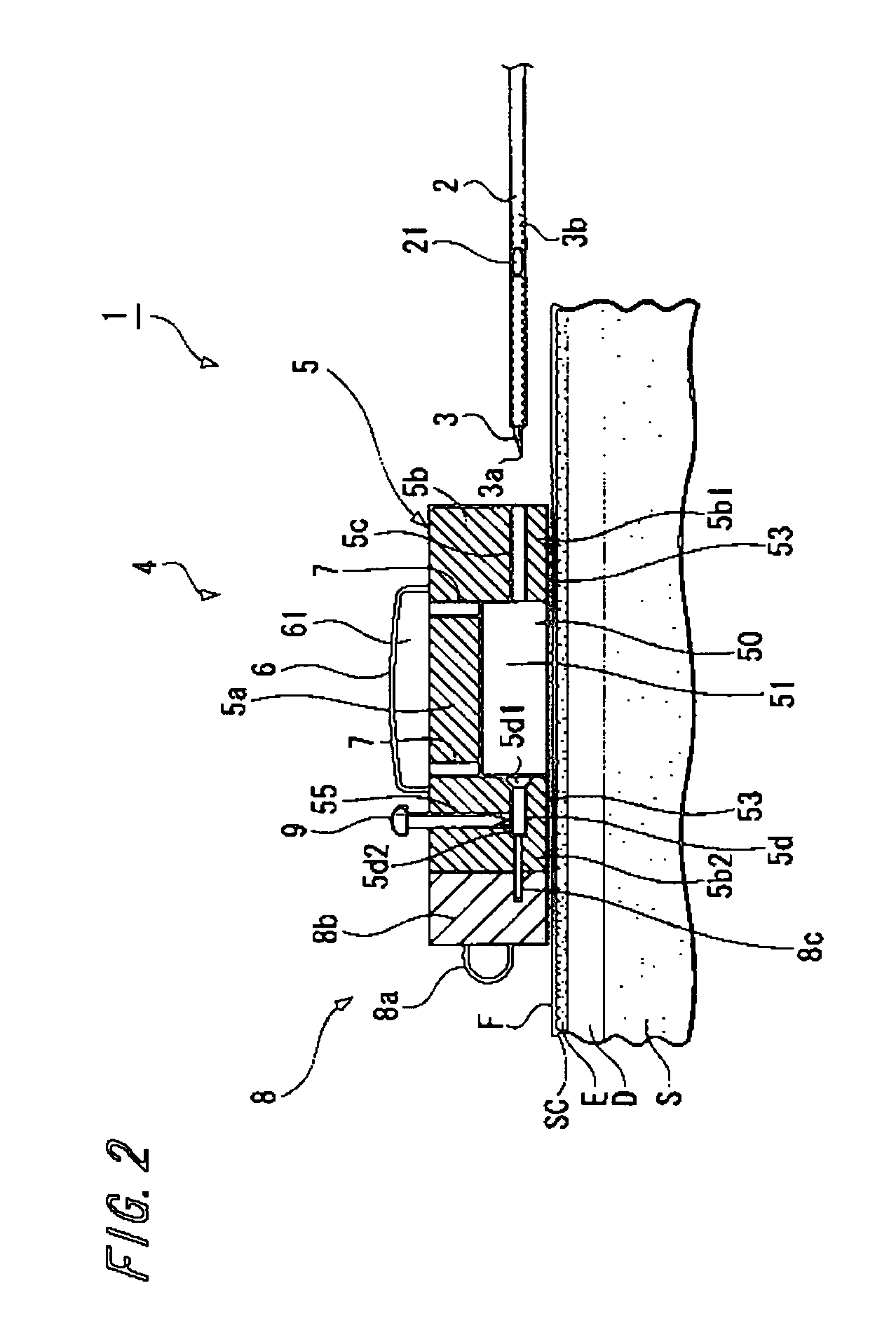
[0060]FIG. 1 is a perspective view showing a first exemplified embodiment of a puncture device 1 of the present invention. Also, FIG. 2 is a cross-section view showing a first exemplified embodiment of the puncture device 1 of the present invention. Also, FIG. 3 and FIG. 4 are diagrams (cross-section views) for explaining usage of the puncture device shown in FIG. 2. It should be noted that it will be explained hereinafter on an assumption that the upside in FIG. 1 to FIG. 4 is made to be “rear end” and the downside thereof is made to be “tip”.

[0061] The puncture device shown in FIG. 1 is constituted by a catheter 2, a puncture needle 3 and skin deforming means 4.

[0062] The skin deforming means 4 is constituted by a fixing portion 5 and a suction means 6.

[0063] The fixing portion 5 is provided with a tabular bottom face portion 5a and a peripheral wal...

second exemplified embodiment

[0121] Next, it will be explained with respect to a second exemplified embodiment of the puncture device 1 of the present invention.

[0122]FIG. 5 is a cross-section view showing the second exemplified embodiment of the puncture device 1 of the present invention.

[0123] Hereinafter, it will be explained with respect to the puncture device 1 of the second exemplified embodiment mainly about differences from the puncture device of aforesaid first exemplified embodiment and with respect to similar matters, the explanations thereof will be omitted.

[0124] In this exemplified embodiment, there is formed at a tip portion of the catheter 2 with the medical agent supplying opening 21. Also, there is mounted at a position apart from the tip portion of the catheter 2 by a predetermined distance d with a ring-shaped positioning member along the circumference of the catheter 2.

[0125] Also, the edge portion of the body portion 3b of the puncture needle 3 is inserted and attached in the vicinity ...

third exemplified embodiment

[0146] Next, it will be explained with respect to a third exemplified embodiment of the puncture device 1 of the present invention.

[0147]FIG. 9 is a cross-section view showing the third exemplified embodiment of the puncture device 1 of the present invention.

[0148] Hereinafter, it will be explained with respect to the puncture device 1 of the third exemplified embodiment mainly about differences from the puncture device of aforesaid first exemplified embodiment and with respect to similar matters, the explanations thereof will be omitted.

[0149] In this exemplified embodiment, a puncture needle 3′ is constituted by a needlepoint 3a and a body portion 3b having a hollow portion. Also, there is formed on the body portion 3b along the longitudinal direction with a slit (or slot) for separating the catheter 2 inserted in and attached on the hollow portion.

[0150] Also, there is mounted at a position apart from the needlepoint 3a by a predetermined distance d with a ring-shaped positio...


PUM


Abstract

To provide a puncture device in which a puncture needle is stuck into a predetermined region certainly and an indwelling device can be indwelled, the puncture device is provided for puncturing skin (dermis) by a puncture needle. This puncture device is provided with a puncture needle, an indwelling device indwelled in the skin by the puncture needle, a skin deforming mechanism for deforming the skin which is provided with a fixing portion having a space in an inside constituted by a bottom face portion and a peripheral wall portion 5b. In addition, an insertion portion for inserting the puncture needle is formed at the peripheral wall portion, the puncture needle is inserted from the insertion portion, and the skin deformed into the space by the skin deforming mechanism is adapted to be punctured.

Description

TECHNICAL FIELD [0001] The present invention relates to a puncture device and relates to a puncture device which is used to puncture a predetermined region, for example, a dermis by puncturing from a skin surface. BACKGROUND ART [0002] It is known that the dermis has a high density of capillary blood vessel when compared with an epidermis or a subcutis and also a lymph vessel end exists therein, so that in particular, a medical agent injected thereto directly is shifted to a blood vessel or a lymph vessel and an absorption speed thereof being absorbed in the body fluid is speedy. In particular, it is possible in the dermis to make a medical agent using a macromolecular substance such as hormone, antibody drug, cytokine and the like to be absorbed into the blood efficiently. Also, it is known that the dermis is a place of efficient immunity and it is possible to make a saving of applied dose of vaccine or to strengthen sensitization of a weak vaccine. [0003] Also, it is known for adu...

Claims


Application Information

Patent Timeline
Patent Type & Authority Applications(United States)
IPC IPC(8): A61M5/32
CPCA61B17/3415A61M37/00A61M5/425
Inventor SONODA, YUTAROKAWANISHI, TETSURO
Owner TERUMO KK
Why Eureka
Try Eureka