

Multipurpose knot pusher
- Summary
- Abstract
- Description
- Claims
- Application Information
AI Technical Summary
Benefits of technology
Problems solved by technology
Method used
Image

Examples
first embodiment
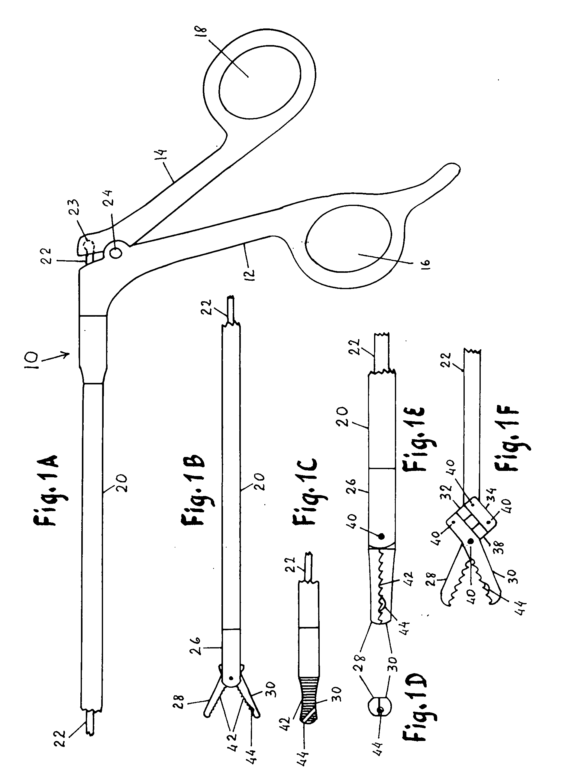
[0053] Referring now to the drawings and particularly to FIG. 1A the handle portion of the invention 10 is shown. This portion includes two arms 12 and 14 provided with two finger openings 16 and 18 for engaging the user's fingers. Arm 12 is fixed in relation to tubular shaft 20, and arm 14 is movable as it moves on pivot 24 to activate connecting rod 22 by means of a ball and socket joint 23.
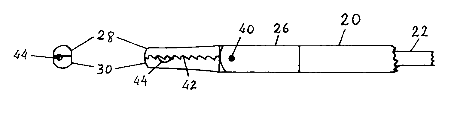
[0054] As illustrated in FIG. 1B the tubular shaft 20 terminates at the distal portion of the device 26 which is provided with two scissors-type elongated jaws 28 an 30 that are activated by the connecting rod 22. Each jaw has transverse serrations 42 and the lower jaw is provided with an oblique groove 44. As illustrated in FIG. 1C the oblique groove runs from one side of the lower jaw to the tip of the jaw at an angle of 40 degrees with the long axis of the jaw. FIG. 1D illustrates the tip of the instrument with the jaws 28 and 30 in a closed position and showing the lower end of the oblique ...
third embodiment
[0056]FIG. 3A illustrates the present invention 30 with a handle portion 311 that includes two arms 312 and 314 provided with finger openings 316 and 318. There is an axis pivot 322 for the movable shaft 320 which slides back and forth on fixed shaft 321. The distal portion of the instrument shows a movable jaw 328 and a fixed jaw 330. Both jaws are provided with transverse serrations 342 and 346. The lower jaw shows the upper end of an oblique groove 344. FIG. 3B shows the lower jaw 330 in continuation with the fixed shaft 321 and provided with transverse serrations 342 and an oblique groove 344. FIG. 3C shows the jaws in a closed position forming part of the movable and fixed shafts 320 and 321. It also shows the upper end of the oblique groove 344. FIG. 3D demonstrates the moving mechanism of the upper jaw which is connected to movable shaft 320 by means of a pivot pin 327. Upper jaw has a short extension 329 connected to lower jaw 330 by a pivot pin 331. This mechanism opens and...
fourth embodiment
[0057]FIG. 4A illustrates the present invention which consists of a clamp 4 with two activating arms 410 and 420 provided with finger openings 412 and 422, and hemostat-type ratchets 411 and 421. These activating arms open and close the long jaws 414 and 424. The lower jaw 414 has an oblique groove near its tip and both jaws are smooth with no serrations. FIG. 4B is an upper view of the lower jaw 414 showing an oblique groove 444 near its tip. FIG. 4C is a front view of the tip of the instrument showing the lower end of the oblique groove 444. FIG. 4D shows the long jaws of the instrument in a closed position with the upper end of the oblique groove 444.
[0058]FIG. 5 illustrates the first embodiment of the present invention 6 in preparation for the pushing down of the first half hitch 3 . The threads 4 and 5 are coming out of the laparoscopic cannula 7, and are hold down between the thumb and index finger in a rather loose fashion. In this case the long end 4 is acting as a post and ...
PUM
 Abstract
Description
Claims
Application Information