Powered adjustable wrench

a technology of adjustable wrenches and wrenches, which is applied in the field of wrenches, can solve the problems of vicarious control, limited prior art wrenches, and certain suffering of powered adjustable wrenches, and achieve the effect of improving control characteristics and operating more efficiently

Inactive Publication Date: 2007-07-12
PICONE PRODS
View PDF4 Cites 1 Cited by
  • Summary
  • Abstract
  • Description
  • Claims
  • Application Information

AI Technical Summary

Benefits of technology

[0011] It is therefore an object of the present invention to provide for a novel and improved powered adjusta

Problems solved by technology

However, the powered adjustable wrenches of the prior art suffer certain drawbacks when utilizing a motor with either pulleys or sprockets and a drive belt or chain respectively, to transmit power to the worm.
Prior art wrenches become limited by design to oversized motors to obtain the necessa

Method used


Image

  • Powered adjustable wrench
  • Powered adjustable wrench
  • Powered adjustable wrench

Examples


first embodiment

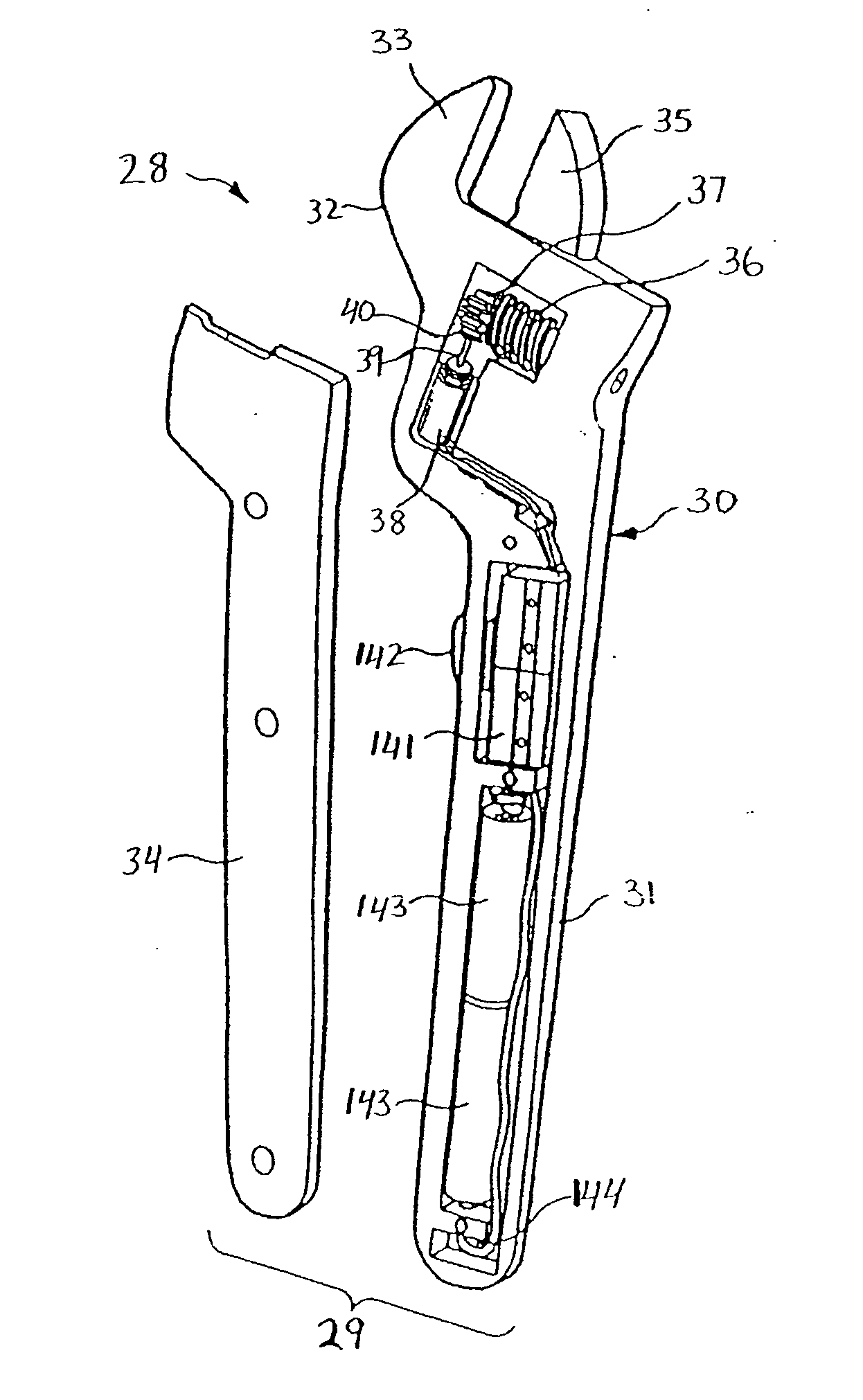
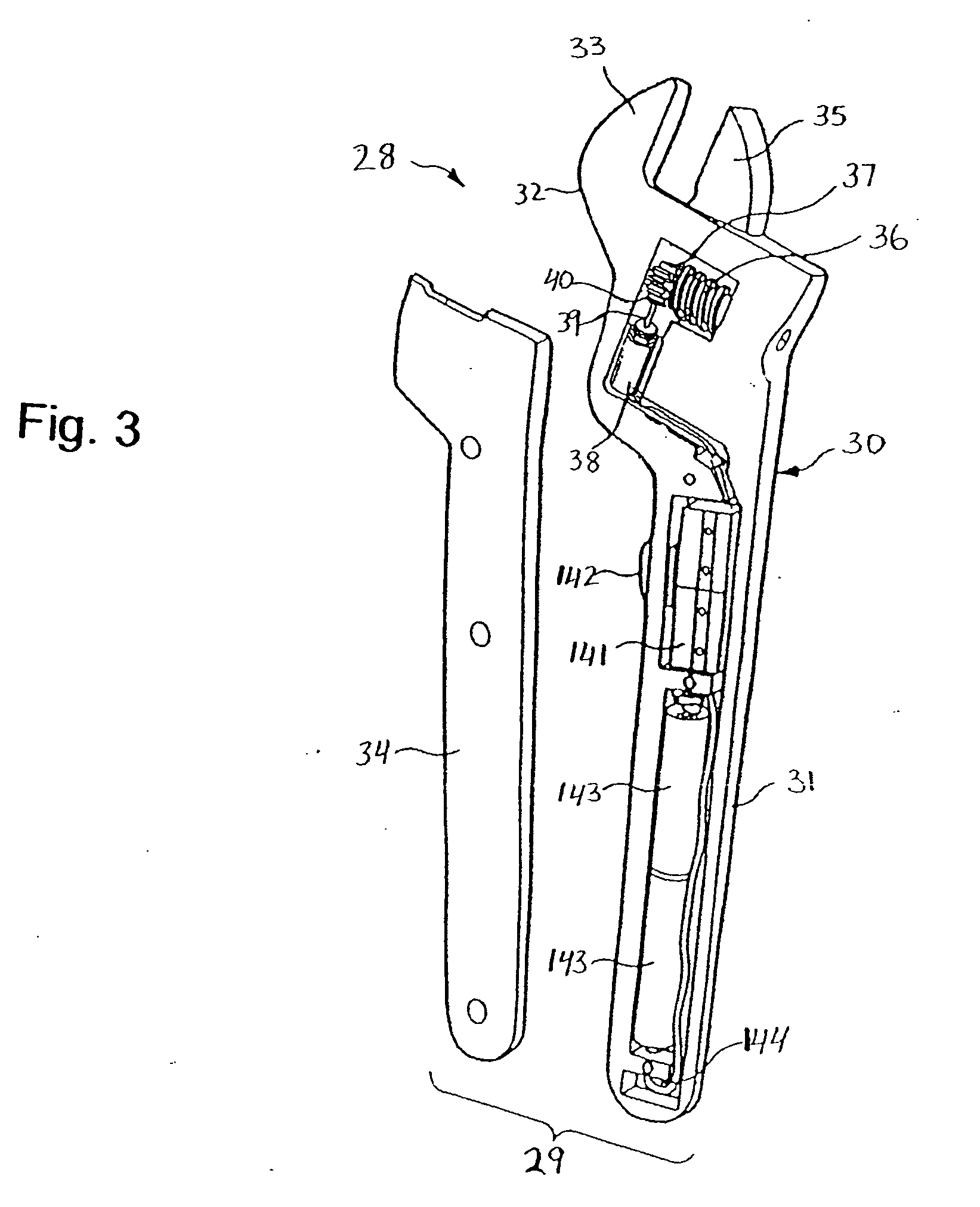
[0040] Referring now to FIG. 3, an improved powered adjustable jaw wrench according to the present invention illustrated generally at 28 and comprises a wrench body 29 including a wrench body member 30 provided with a stationery jaw 33, and a handle cover 34 removably fastened to the wrench body member 30, and a movable jaw 35 adjustable relative to the stationery jaw 33. The movable jaw 35 is formed integral with a toothed rack 45, as shown in FIG. 4. The wrench body member 30 includes a handle portion 31 and a head portion 32. The stationery jaw 33 is integral to the head portion 32. Preferably, the handle portion 31 and the head portion 32 of the wrench body member 30, illustrated further in detail in FIG. 5, form a unitary single-piece part. It will be appreciated by those skilled in the art that the wrench body member 30 may be made of any appropriate material such as metal (steel, aluminum, etc.) or plastic material. The metal wrench body member 30 may be manufactured, prefera...

second embodiment

[0041] In the modified version according to the present invention, illustrated in FIG. 6, the wrench body 29 includes a unitary single-piece wrench body member 30′ and a pair of opposite handle covers 34′ and 34″ removably fastened to the wrench body member 30′, preferably by bolts or screws.

[0042] The powered adjustable jaw wrench 28 according to the present invention further includes a driven mechanism comprising a worm gear 36 and a first rotatable member both rotatably mounted in the head portion 32 of the wrench body member 30 coaxially with respect to each other. The worm gear 36 is operably connected to the toothed rack 45 of the movable jaw 35 so that the rotatable movement of the worm gear 36 is transformed into the linear movement of the movable jaw 35. In the first embodiment of the present invention, as illustrated in FIGS. 3 and 7, the first rotatable member is in the form of a first toothed indexing wheel 37 mounted on a stationary shaft 51 coaxially relative to the wo...

third embodiment

[0055] In accordance with the present invention, various arrangements of mechanical drives and solenoid drives in conjunction can be utilized for the linear indexing power source. In accordance with the present invention, illustrated in FIG. 10, two solenoids 38 are used and are attached by their respective shaft plungers 39 to a single shared first pallet member 40. The independent alternating push and pull forces of the combined solenoids 39 provide the linear movement of the single first pallet member 40. The first pallet member 40 incrementally drives the mating index wheel 37, causing incremental rotatory clockwise or counter-clockwise movement of the worm 36.


PUM


Abstract

A powered adjustable jaw wrench comprises a wrench body having a handle portion and a head portion defining a stationary jaw, a movable jaw reciprocally mounted to the head portion, a driven mechanism operably connected to the movable jaw, and a drive mechanism mounted to the body member and including a power source and an indexing mechanism. The driven mechanism includes a worm driving the movable jaw and an indexing wheel operably connected to the worm gear. The indexing mechanism is driven by the power source and includes an oscillating pallet member. The pallet member incrementally drives the indexing wheel so as to convert an oscillating movement of the pallet member into an incremental rotatable movement of the indexing wheel.

Description

CROSS-REFERENCE TO RELATED APPLICATION [0001] This Application claims the benefit under 35 U.S.C. 119(e) of U.S. Provisional Application No. 60 / 757,485 filed on Jan. 10, 2006 by John Picone.BACKGROUND OF THE INVENTION [0002] 1. Field of the Invention [0003] The present invention relates generally to wrenches and, more particularly, to a powered adjustable wrench having a sliding jaw. [0004] 2. Description of the Prior Art[0005] A powered adjustable jaw wrench having a sliding jaw and a stationary jaw is known in the prior art. As illustrated in FIG. 1, the powered adjustable jaw wrench 10 of the prior art comprises a wrench body 11 including a wrench body member 12 provided with an integral stationary jaw 15, and a handle cover 16, a moveable jaw 17 adjustable relative to the stationary jaw 15. A handle portion 13 and a head portion 14 of the wrench body member 12 form a unitary single-piece part. A worm gear 19 and a sprocket 18 rotatable mounted in the head portion 14 of the wrenc...

Claims


Application Information

Patent Timeline
IPC IPC(8): B25B21/00B25B13/16B25B17/00
CPCB25B13/14
Inventor PICONE, JOHN A.
Owner PICONE PRODS
Why Eureka
Try Eureka