Locking transmission for a vehicle, and vehicle including same

Inactive Publication Date: 2007-07-12
HONDA MOTOR CO LTD
View PDF4 Cites 11 Cited by
  • Summary
  • Abstract
  • Description
  • Claims
  • Application Information

AI Technical Summary

Benefits of technology

[0011] According to the first aspect of the invention, the parking lock mechanism is driven in an interlocking relationship with the working portion of the shift change mechanism. Therefore, the parking lock mechanism is commonly formed with an upstream side portion of a power transmission system of the shift change mechanism, and is driven making use of an operation means of the shift change mechanism, actuator and so forth as well as the working portion. Consequently, the parking lock mechanism is compactly incorporated in the shift change mechanism without requiring operation means, an actuator and so forth dedicated for exclusive use for parking gear locking. Consequently, the overall size of the internal combustion engine is reduced.
[0012] Further, if the shift change mechanism is set to the parking position, then the rotary shaft of the transmission is locked by the parking lock mechanism, thereby restricting rotation of the rotary shaft. Consequently, the operation thereof is simplified and convenient, and the operability is good.
[0014] According to the second aspect of the invention, the pawl portion of the locking member is driven in an interlocking relationship with the working portion of the shift change mechanism. In addition, the pawl portion is engaged with the locking portion provided integrally on the output power shaft of the transmission, thereby restricting rotation of the output power shaft. Consequently, rotation of the output power shaft is restricted with certainty with a simple configuration.
[0018] According to the fourth aspect of the invention, the distance of the power point of the lever, which is a locking member from the fulcrum, is set greater than the distance of the pawl portion, which is the point of action, from the fulcrum. Therefore, by the principle of the lever, even where the parking lock mechanism is small in size, engagement and disengagement of the pawl portion with and from the locking portion of the output power shaft can be performed smoothly with doubled force.
[0022] According to the sixth aspect of the invention, the end portion of the shift spindle is formed as a separate removable member, and the parking lock mechanism is connected to the end portion of the shift spindle so as to be interlocked with the shift spindle. Therefore, by connecting the parking lock mechanism to the end portion so as to form a unit, the assemblage performance is enhanced.

Problems solved by technology

As a result, rotation of the input power shaft is restricted.
Since the conventional parking lock mechanism is configured such that a power transmission system is formed as an independent apparatus which is separate from a shift change mechanism, and is driven by an actuator provided for exclusive use by the independent apparatus, it includes a great number of parts and increases the size of the internal combustion engine.
As a result, rotation of the rotary shaft is restricted.
Further, if the shift change mechanism is set to the parking position, then the rotary shaft of the transmission is locked by the parking lock mechanism, thereby restricting rotation of the rotary shaft.
As a result, rotation of the output power shaft is restricted.
Consequently, rotation of the output power shaft is restricted with certainty with a simple configuration.

Method used


Image

  • Locking transmission for a vehicle, and vehicle including same
  • Locking transmission for a vehicle, and vehicle including same
  • Locking transmission for a vehicle, and vehicle including same

Examples


Embodiment Construction

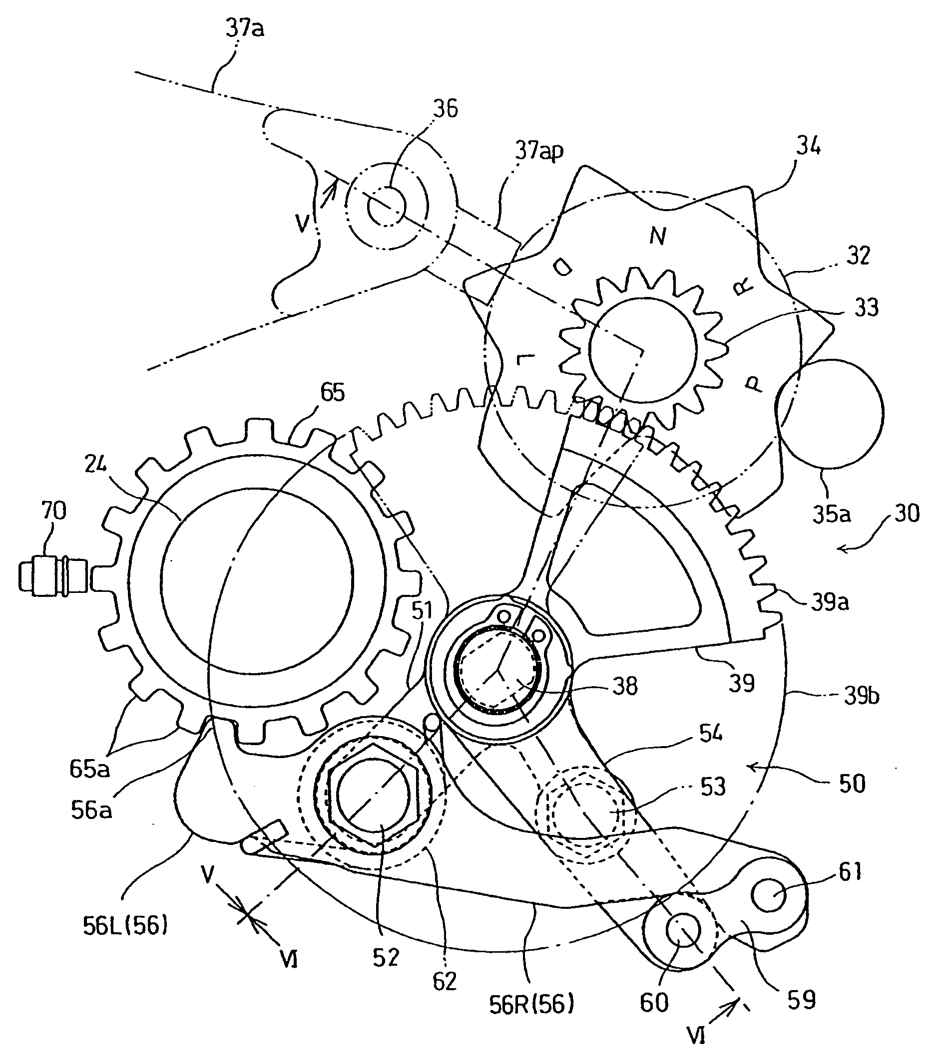
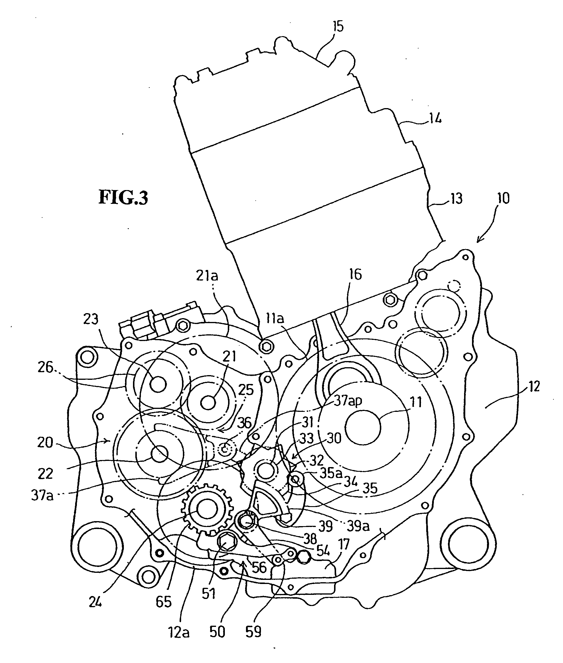
[0036] A selected illustrative embodiment of the invention will now be described in some detail, with reference to the drawings. It should be understood that only structures considered necessary for clarifying the present invention are described herein. Other conventional structures, and those of ancillary and auxiliary components of the system, are assumed to be known and understood by those skilled in the art. Directional descriptions are provided with respect to the point of view of an operator of the vehicle. For example, a disclosure of “forward” refers to the forward operating direction of the vehicle

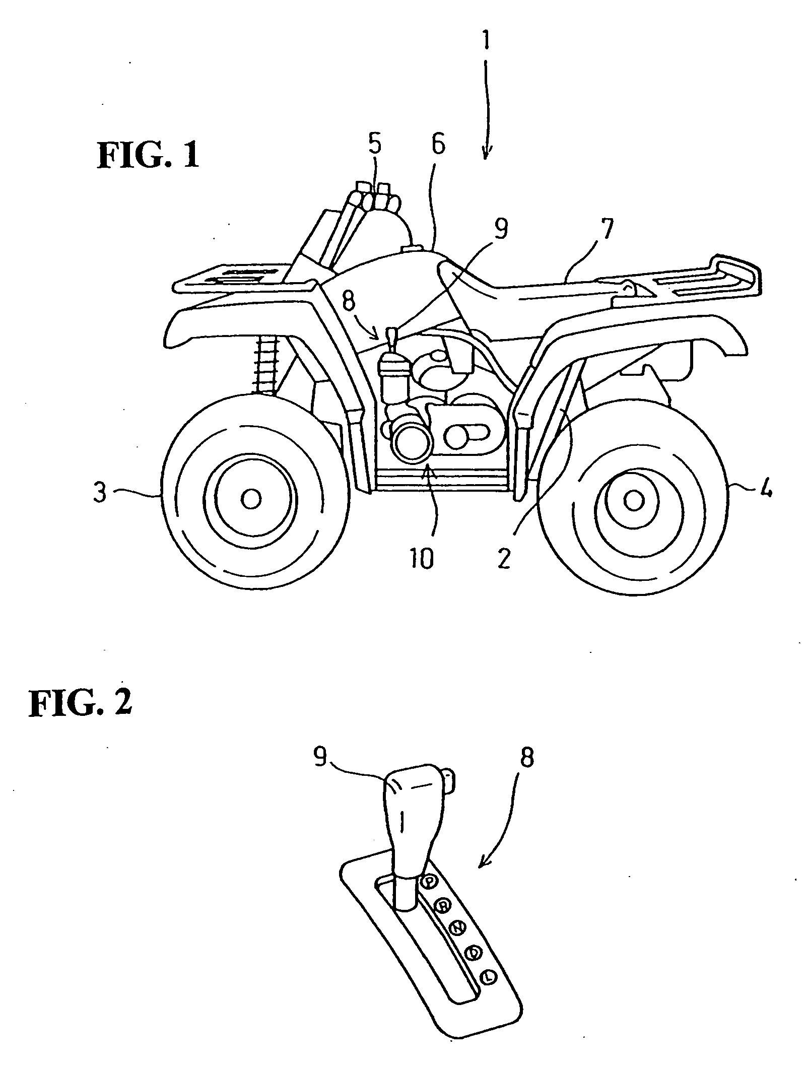
[0037] A four-wheel, saddle type all-terrain vehicle (ATV) 1 for traveling on rough or irregular ground, and which incorporates an internal combustion engine including a transmission according to the present embodiment, is shown in FIG. 1.

[0038] The vehicle 1 includes a vehicle body frame 2, with a pair of front wheels 3, 3 disposed on opposite sides of a front portion of the ve...


PUM


Abstract

A transmission for an internal combustion apparatus is provided in which a parking lock mechanism is commonly formed with an upstream side portion of a power transmission system of a shift change mechanism, whereby the number of parts is reduced and the parking lock mechanism is compactly incorporated therein to achieve miniaturization of the internal combustion engine. The transmission in which a shift change mechanism performs a shift change in response to an operation of a gear selecting apparatus is configured to include a parking lock mechanism which is driven in an interlocking relationship with a working portion of the shift change mechanism, and if the shift change mechanism is set to the parking position, then a rotary shaft of the transmission is locked against rotation by the parking lock mechanism thereby restricting rotation of the rotary shaft.

Description

CROSS-REFERENCE TO RELATED APPLICATIONS [0001] The present invention claims priority under 35 USC 119 based on Japanese patent application No. 2006-004091, filed on Jan. 11, 2006. The subject matter of this priority document is incorporated by reference herein. BACKGROUND OF THE INVENTION [0002] 1. Field of the Invention [0003] The present invention relates to a transmission for use with an internal combustion engine, in which the transmission includes a parking lock mechanism, and to a vehicle including the locking transmission. [0004] 2. Description of the Background Art [0005] Various examples of transmissions for internal combustion engines have been proposed, in which a parking position of the transmission can be selected in response to an operation of a shift lever, and in which the transmission includes a parking lock mechanism for restricting rotation of a drive shaft. Such restriction takes place when the vehicle is stopped, the parking position is selected, and then the in...

Claims


Application Information

Patent Timeline
IPC IPC(8): B60W10/10B60W10/18B60T1/06F16H63/34
CPCF16H63/18Y10T74/19279F16H63/3416
Inventor FUJIMOTO, YASUSHIITO, KATSUHIKOMIZUNO, KINYA
Owner HONDA MOTOR CO LTD
Why Eureka
Try Eureka