High lift and high strength aerofoil

Inactive Publication Date: 2007-07-12
HUBBARD ADRIAN ALEXANDER
View PDF0 Cites 18 Cited by
  • Summary
  • Abstract
  • Description
  • Claims
  • Application Information

AI Technical Summary

Benefits of technology

[0007]FIGS. 2, 2A and 2B illustrate a preferred embodiment of the stepped section, incorporated into a high aspect ratio aircraft wing.
[0

Problems solved by technology

Conventional aerofoils have usually quite small thickness compared to their chord and it is diffi

Method used


Image

  • High lift and high strength aerofoil
  • High lift and high strength aerofoil
  • High lift and high strength aerofoil

Examples


Embodiment Construction

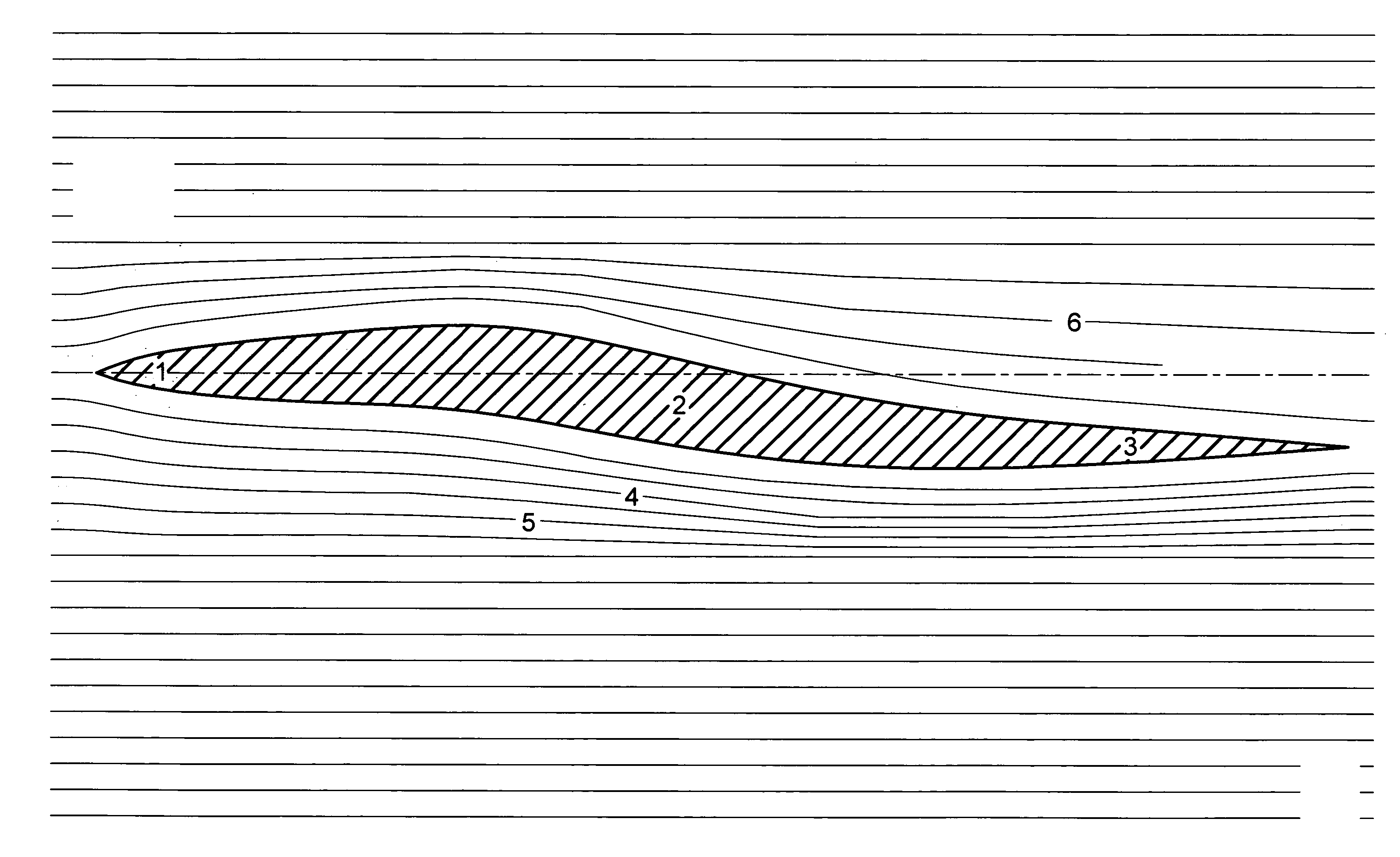
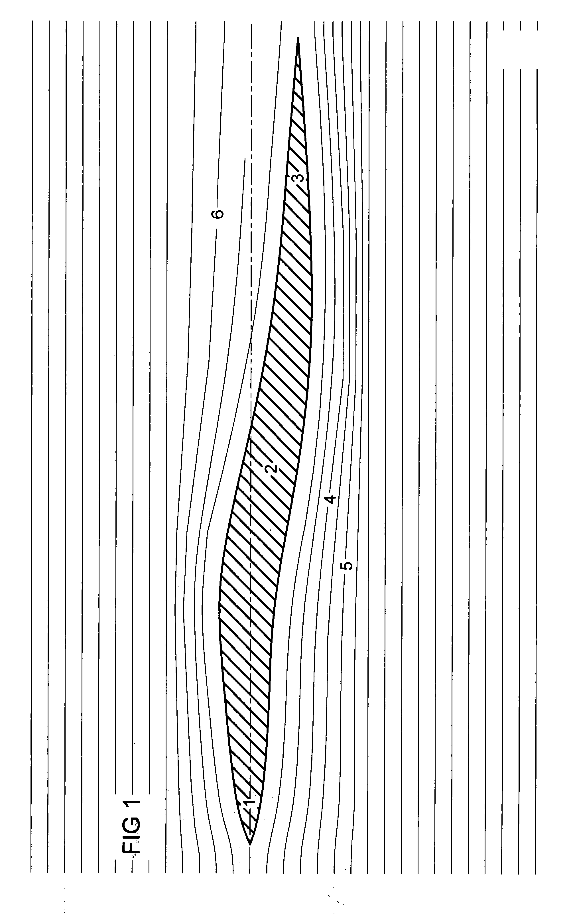
[0012] Referring to the drawings the aerofoil has a leading edge 1, a stepped section 2 and a trailing edge 3. The step 2 creates compression 4 on the under surface of the section giving a high pressure area 5 below the aerofoil; above the aerofoil is a low pressure area 6, see FIG. 1.

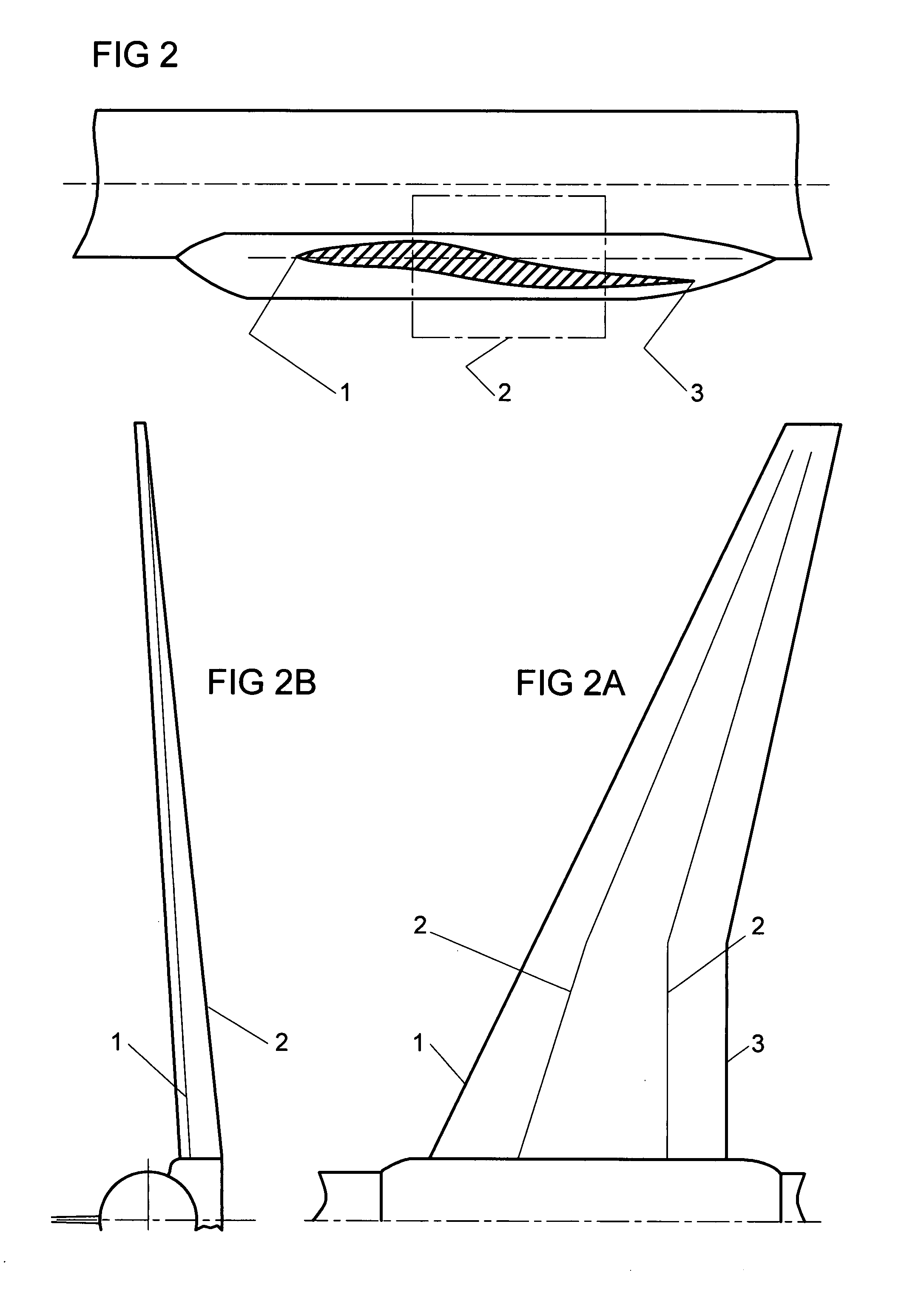
[0013] Referring to FIG. 2 the stepped aerofoil is incorporated into a high aspect ratio aircraft wing. The step depth is between half of wing thickness and once wing thickness at the wing root. The step tapers, from maximum depth inboard, to zero depth at the wing tip, see FIGS. 2A and 2B.

[0014] Referring to FIG. 3 the stepped aerofoil is incorporated into a low aspect ratio aircraft wing. The step depth is between once wing thickness and twice wing thickness at the wing root. The step tapers, from maximum depth inboard, to zero depth at the wing tip, see FIGS. 3A and 3B.

[0015] Referring to FIG. 4 the stepped aerofoil is incorporated into a delta aircraft wing. The step depth is between twice wing ...


PUM


Abstract

A high lift stepped aerofoil section, incorporating a leading edge 1, trailing edge 3 and a step 2 to provide a higher vertical component in its construction; the aerofoil has greater perceived root thickness giving greater lift through compression 4 on the aerofoil under surface. The section has high pressure area 5 below the aerofoil and low pressure area 6 above the aerofoil. The aerofoil has much higher strength on all axes than conventional aerofoil sections.

Description

CROSS REFERENCE TO RELATED APPLICATIONS [0001] US Priority Document:—10 / 780,663 STATEMENT REGARDING FEDERALLY SPONSORED RESEARCH OR DEVELOPMENT [0002] Not Applicable REFERENCE TO MICROFICHE APPENDIX [0003] Not Applicable BACKGROUND OF THE INVENTION [0004] Conventional aerofoils have usually quite small thickness compared to their chord and it is difficult to provide adequate strength if they are to be efficient, especially in high speed operation. This invention relates to a high lift aerofoil, incorporating a step, to provide a higher vertical component in its construction. The aerofoil has greater perceived root thickness giving greater lift through compression on the aerofoil under surface, with low pressure on the upper surface, and also giving much higher strength to the aerofoil on all axes compared to conventional aerofoil sections. BRIEF SUMMARY OF THE INVENTION [0005] A stepped section aerofoil profile having a chord and a thickness, and comprises a leading edge portion, a ...

Claims


Application Information

Patent Timeline
IPC IPC(8): B64C3/14B64C11/18B64C27/467F04D29/38
CPCB64C3/14B64C11/18F04D29/384B64C2003/142B64C27/467
Inventor HUBBARD, ADRIAN ALEXANDER
Owner HUBBARD ADRIAN ALEXANDER
Why Eureka
Try Eureka