
Display device

a display device and display screen technology, applied in the field of display devices, can solve the problems of deteriorating display quality, irregularity of images, deterioration of display image quality, etc., and achieve the effect of high display quality

Active Publication Date: 2007-07-12
PANASONIC LIQUID CRYSTAL DISPLAY CO LTD +1
View PDF3 Cites 29 Cited by
  • Summary
  • Abstract
  • Description
  • Claims
  • Application Information

AI Technical Summary

Benefits of technology

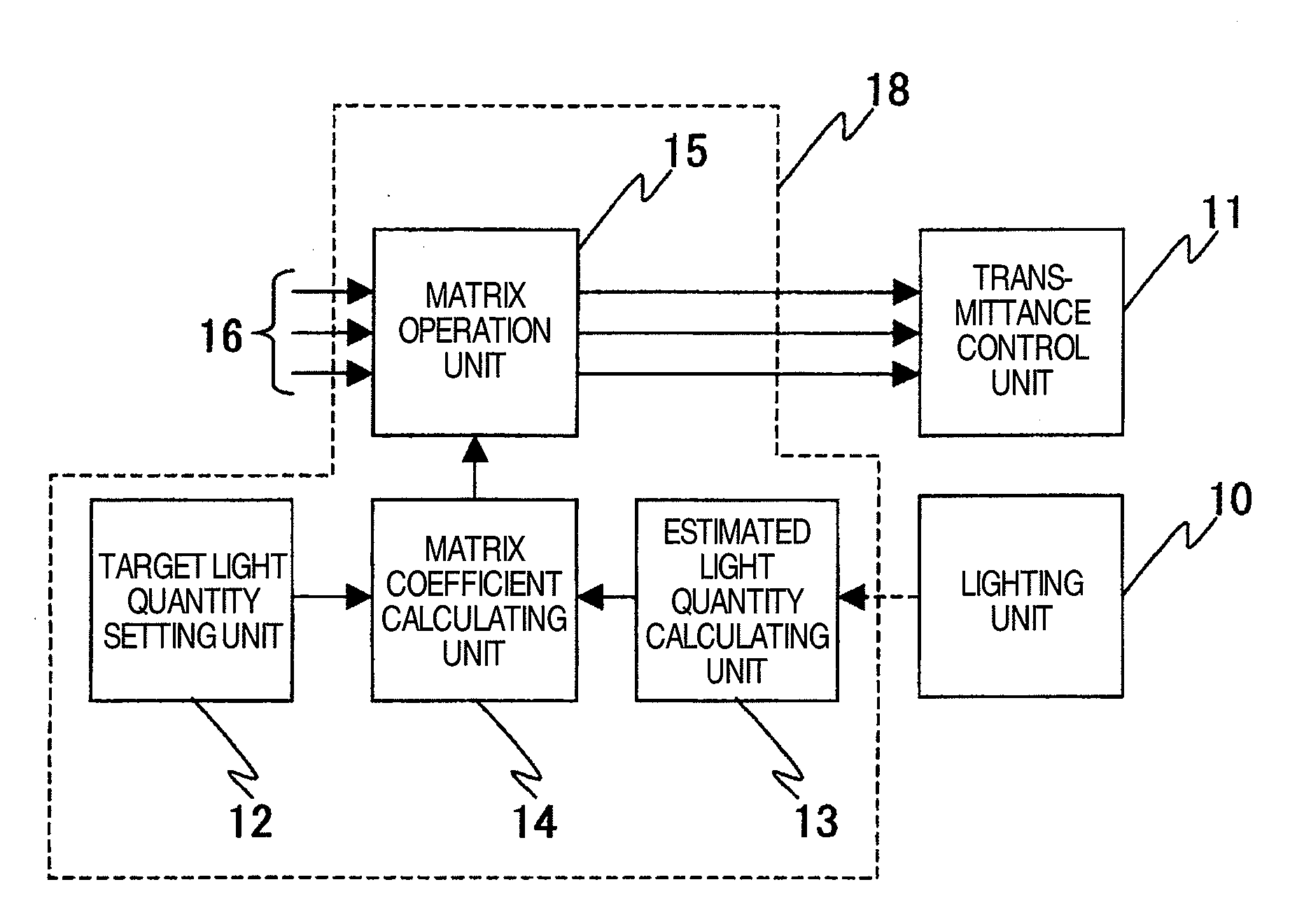
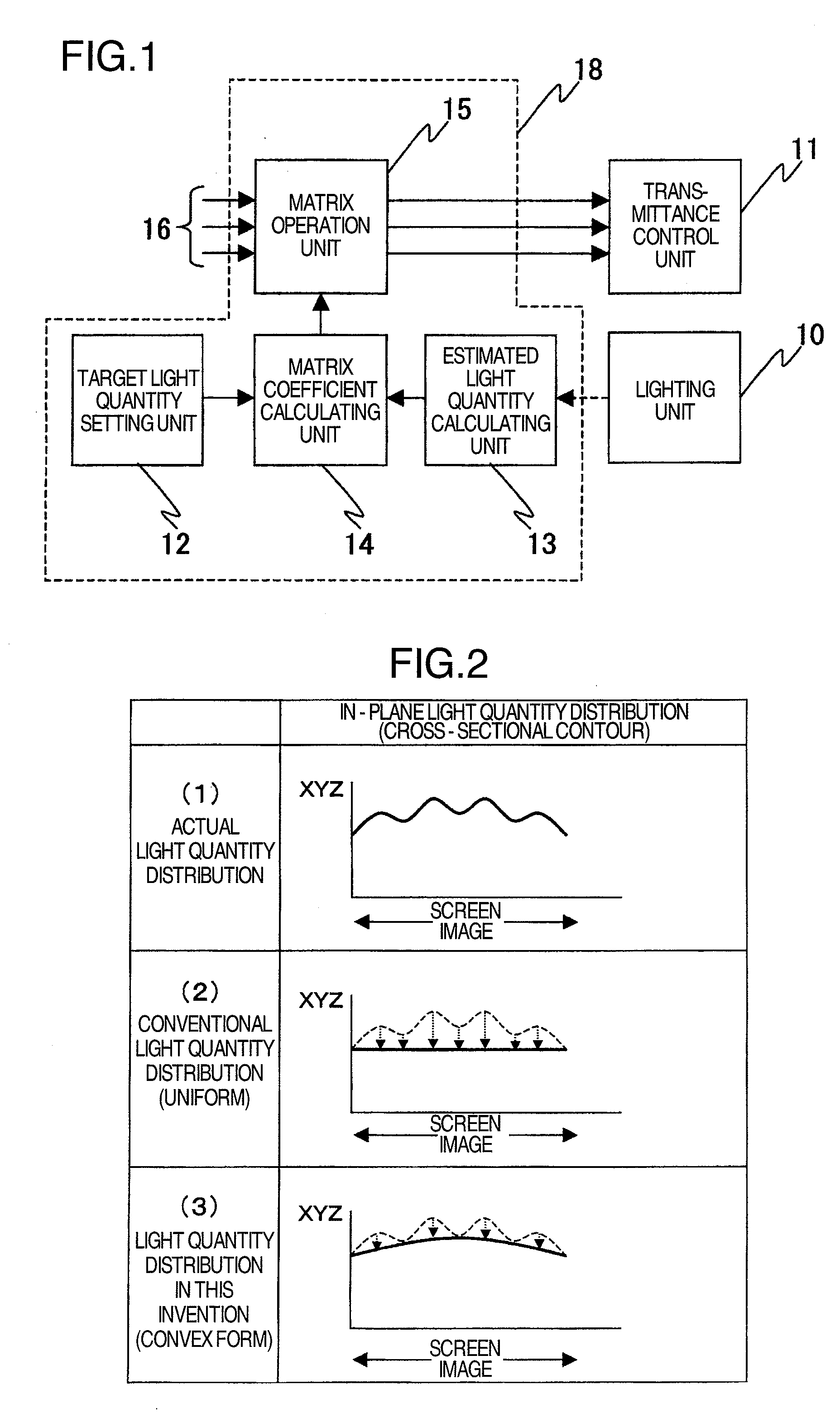
[0018] The present invention corrects irregularity caused by the lighting unit by signal processing so that light quantity distribution in the displayed image becomes identical to a target light quantity distribution. This is effective in realizing a high display quality.

Problems solved by technology

If some characteristics are not uniform, the rays incident on the liquid crystal panel are not uniform, and rays output from the liquid crystal panel under a control become irregular, resulting in deterioration of quality of the displayed image.
If it is impossible to provide sufficient scattering of light, irregularity occurs on an image.
When forming a backlight by arranging a large number of LED devices in one plane, it ought to be noted that the variation in characteristics among the devices and the irregularity caused by the optical structure are the factors that deteriorate display quality.
To minimize the variation in characteristics among devices, it is effective to sort devices but this takes sorting instrument and time.
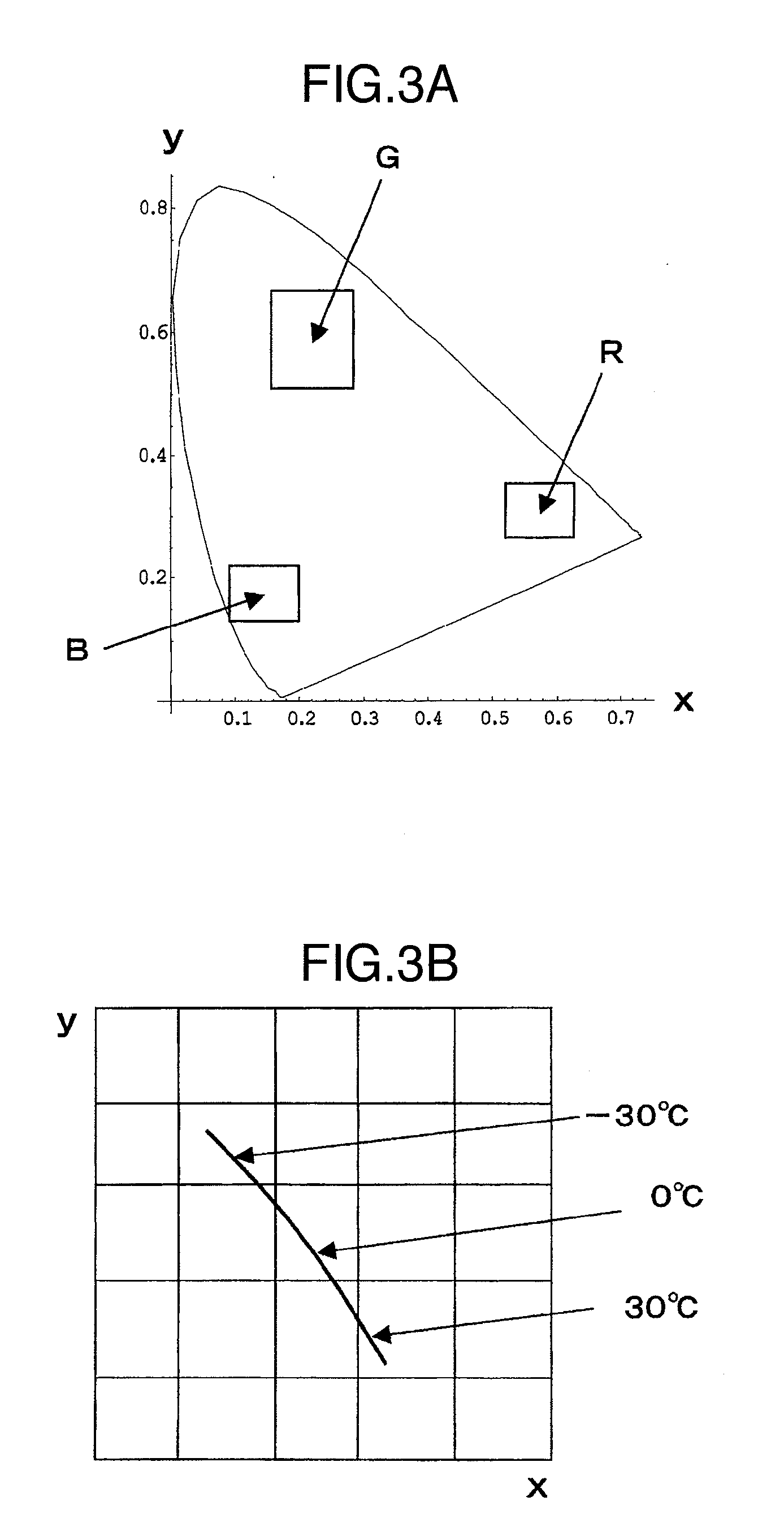
If there is variation in the emission wavelength distribution (spectrum) of the LED, so long as only the luminance and the hue are used as correcting objects, sufficient correction cannot be obtained and irregular color cannot be eliminated.
Secondly, if one takes note of characteristics of signals supplied to a displayed image which is to be the target after correction has been made, generally, the center area of the displayed image tends to be light and the peripheral region dark for reasons of the optical structure.
This suppresses the lighting unit's fundamental capacity of providing the brightness of the center area of the displayed image.

Method used


Image

  • Display device
  • Display device
  • Display device

Examples


Embodiment Construction

[0028] Embodiments of the present invention to carry out the present invention will be described below.

[0029] A display device comprises a backlight for surface lighting by using semiconductor light emitting devices, such as LEDs, and a liquid crystal panel having liquid-crystal-applied transmittance (or reflectance) control devices arranged in a plane. In this display device, the backlight and the liquid crystal panel are stacked together, and a display image is formed by controlling at each pixel the transmittance (or reflectance) of light quantity from the backlight to thereby correct the irregular luminance to improve display quality.

[0030] To clarify the structure and features of the present invention, the factors causing irregularity to occur in a displayed image will be described. To use LEDs for the backlight, signal processing is carried out by considering the (1) magnitude, (2) variation, and (3) changes (in the relation among temperature, elapsed time, driving voltage, ...


PUM


Abstract

A display device configured to realize a high display quality by correcting irregularity, caused by a lighting unit, by signal processing. The target light quantity in a displayed image of the liquid crystal panel is set, the estimated light quantity at each pixel location in the plane of the backlight is calculated, matrix coefficients are calculated based on the estimated light quantity and the target light quantity, image signals are subjected to matrix operations using the matrix coefficients, and the liquid crystal panel is driven by image signals resulting from the matrix operations. Therefore, the light quantity distribution in the displayed image becomes identical to the target light quantity distribution.

Description

BACKGROUND OF THE INVENTION [0001] The present invention relates to a display device for image display by using a backlight and a liquid crystal display in combination. [0002] A liquid crystal display as a display device is configured by combining a backlight and a liquid crystal panel. This backlight illuminates the liquid crystal panel in its whole area or in multiple divided segments. The liquid crystal panel has a structure having arranged in a plane a number of pixels with a function of transmittance control (or reflectance control) by liquid crystal elements, each pixel being provided with a color filter. As the liquid crystal panel is combined with a backlight, the liquid crystal panel becomes a display device capable of displaying color images. [0003] The basic requirement of the backlight is to illuminate the liquid crystal panel uniformly, and the light emission characteristics, which contribute to uniform lighting, include wavelength distribution, luminance, full-width ha...

Claims


Application Information

Patent Timeline
Patent Type & Authority Applications(United States)
IPC IPC(8): G09G3/36
CPCG09G3/3413G09G2320/0233G09G2360/145G09G2320/0646G09G2320/0666G09G2320/0285
Inventor INUZUKA, TATSUKIKANEKO, HIROKI
Owner PANASONIC LIQUID CRYSTAL DISPLAY CO LTD
Learn More