
Moving picture coding and/or decoding systems, and variable-length coding and/or decoding system

a coding and/or decoding system technology, applied in the field of moving picture coding and/or decoding systems, can solve the problems of coded data not being correctly decoded, reversible code contains many useless bits, and has a long average code length. , to achieve the effect of decoding to channel errors, enhancing coding efficiency, and high degree of freedom for bit patterns

Inactive Publication Date: 2007-07-12
KK TOSHIBA
View PDF34 Cites 21 Cited by
  • Summary
  • Abstract
  • Description
  • Claims
  • Application Information

AI Technical Summary

Benefits of technology

[0014] It is therefore an object of the present invention to eliminate the aforementioned problems and to provide a variable length coding and / or decoding system, which can efficiently encode and / or decode data by a small amount of operation and a small memory capacity and which can decode both in forward and backward directions.
[0015] It is another object of the present invention to provide a variable length coding and / or decoding system, which can decrease the number of useless bit patterns to enhance the coding efficiency and which can decode both in forward and backward directions even if synchronization intervals are set every predetermined intervals using stuffing codes.
[0016] It is further object of the present invention to provide a variable length coding and / or decoding system, which can decrease the number of useless bit patterns to enhance the coding efficiency, which can decrease the circuit scale and the amount of operation to efficiently decode by sequentially carrying out the decoding process, and which can decode both in forward and backward directions.

Problems solved by technology

In general, there is a problem in that, if an error is mixed in a variable length code due to a channel error of coded data or the like, a decoding system can not correctly decode the data due to the propagation of influence of the error after the error is mixed therein.
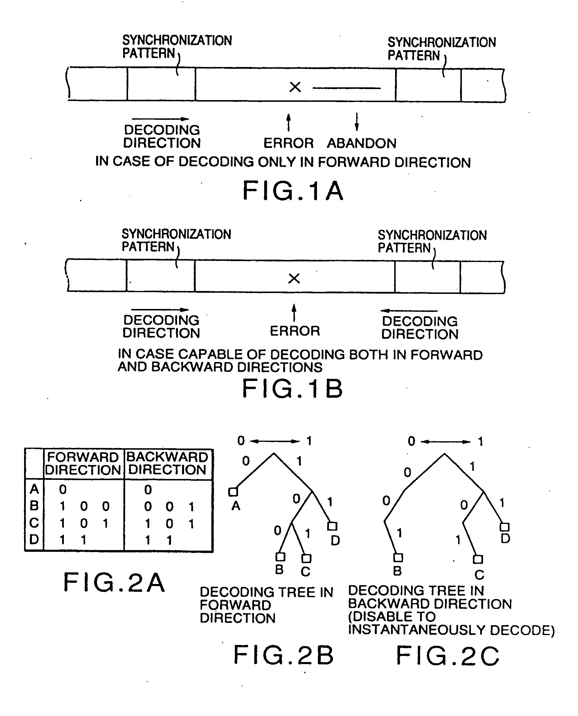
However, even if the synchronization patterns are used, the coded data can not be decoded until the next synchronization pattern is found from the position, at which the coded data can not be correctly decoded due to the error occurring therein as shown in FIG. 1A.
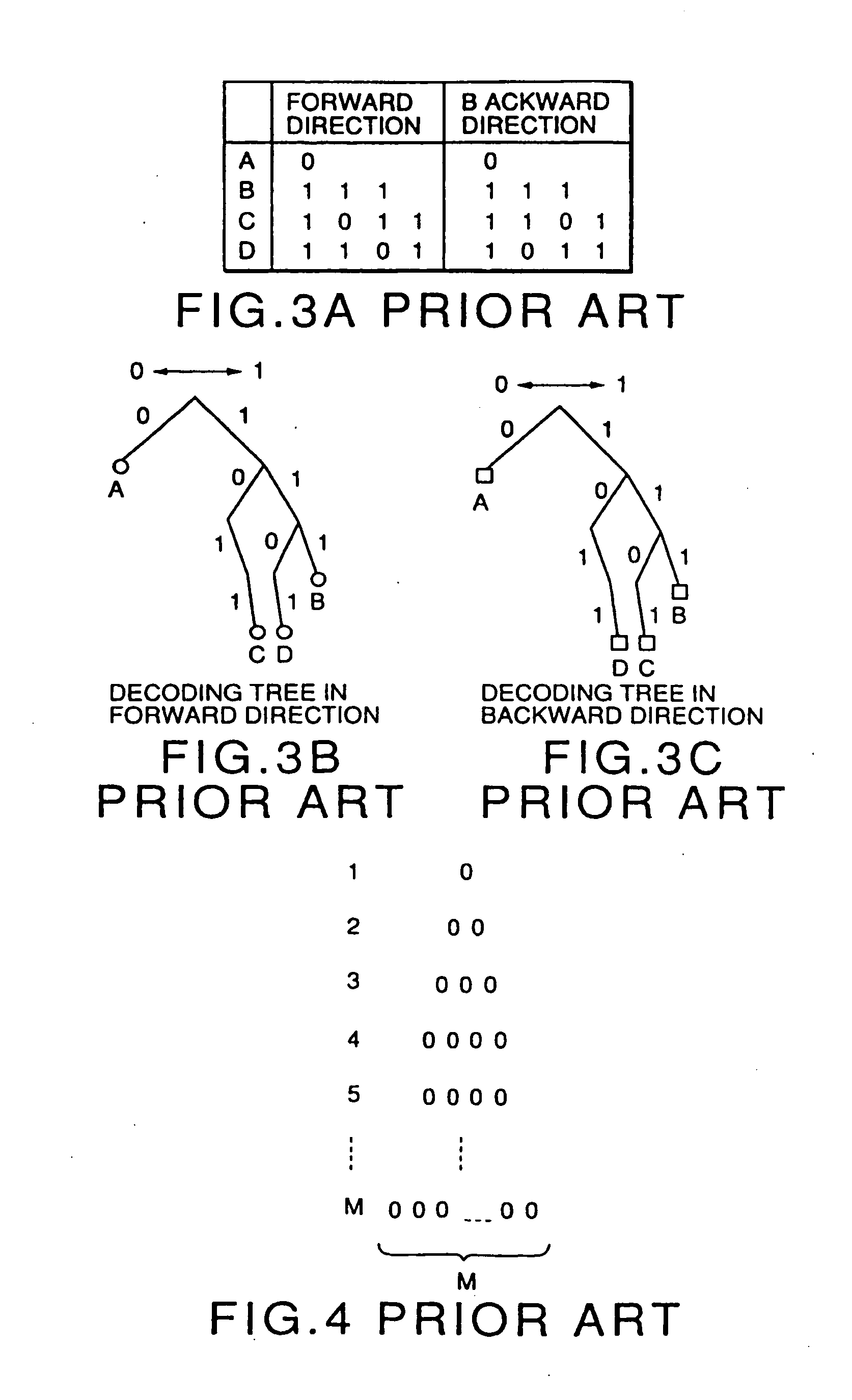
However, this reversible code contains many useless bits to have a long average code length since the bits are added to the ends of the code words of the variable length code, which can be decoded only in the forward direction.
Consequently, the coding efficiency is considerably deteriorated in comparison with the variable length code, which can be decoded only in the forward direction.
There is also a problem in that the conventional reversible code can not be decoded in the backward direction if synchronization intervals are set every predetermined intervals.
In such a case, in the conventional reversible codes, there is a problem in that the backward decoding can not be carried out due to the stuffing bits.
Moreover, when the reversible code is simply decoded, there is a problem in that the circuit scale and the amount of operation have to be twice as large as those in a usual decoding system for variable length codes, which can be decoded only in the forward direction, by the amount decoded in the backward direction.
There is another problem in that the conventional reversible code can not be decoded in the backward direction by syntax of input information as the case may be.
That is, as described above, since the conventional reversible code, i.e., the variable length code capable of being decoded both in the forward and backward directions, is formed by adding bits to the suffix of code words of a variable length code capable of being decoded only in the forward direction, there is a problem in that useless bit patterns are increased to increase an average code length, so that the coding efficiency is considerably deteriorated in comparison with the variable length code capable of being decoded only in the forward direction.
In addition, if the synchronization intervals are set every predetermined intervals using stuffing bits, there is a problem in that the reversible code can not be decoded in the backward direction due to the stuffing bits.
Moreover, if the reversible code is simply decoded, there is a problem in that the circuit scale and the amount of operation have to be twice as large as those in a usual decoding system for variable length codes capable of being decoded only in the forward direction, by the amount decoded in the backward direction, and there is a problem in that it is not possible to decode in the backward direction by the syntax of input information as the case may be.

Method used


Image

  • Moving picture coding and/or decoding systems, and variable-length coding and/or decoding system
  • Moving picture coding and/or decoding systems, and variable-length coding and/or decoding system
  • Moving picture coding and/or decoding systems, and variable-length coding and/or decoding system

Examples


first preferred embodiment

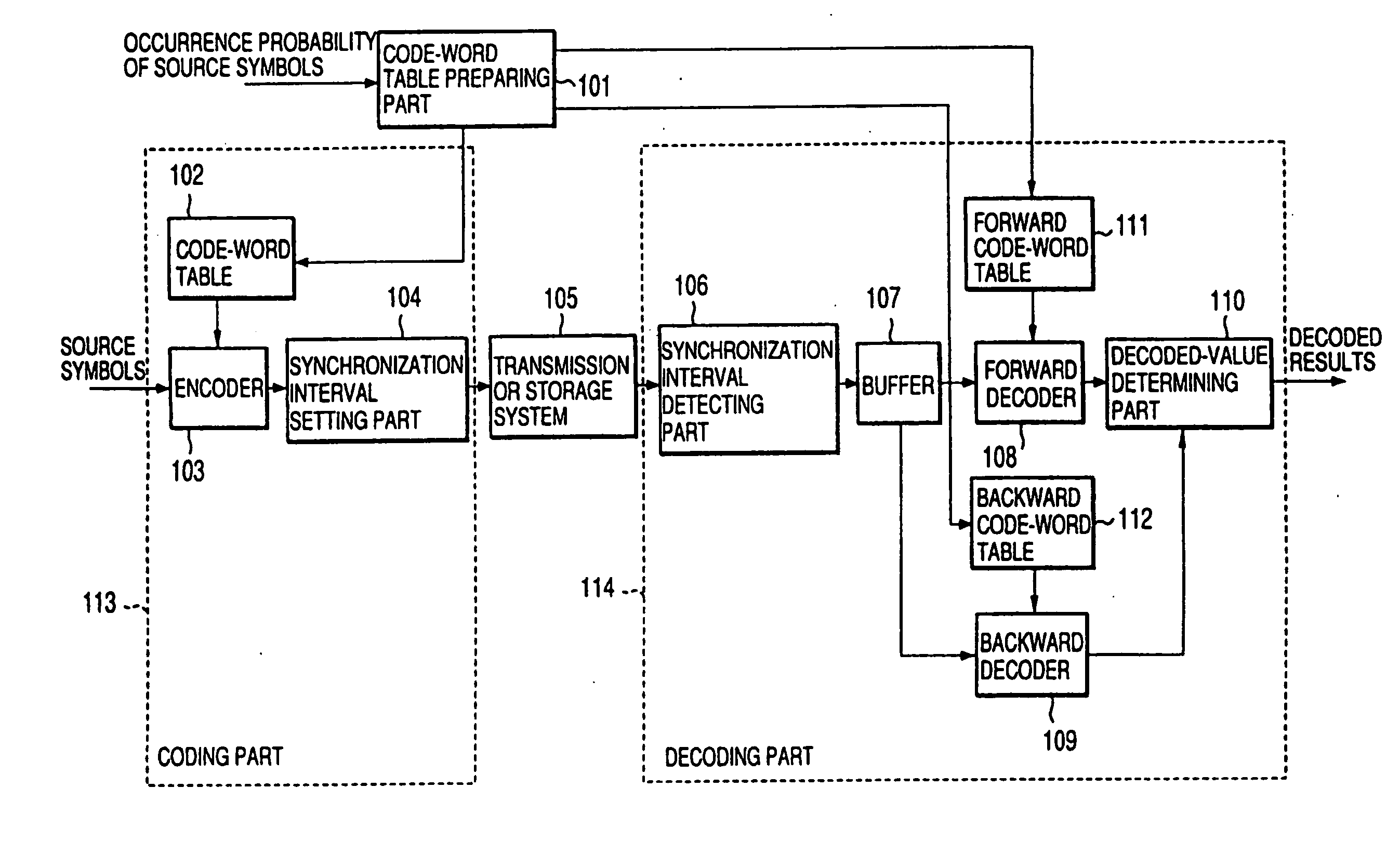
[0148]FIG. 6 is a block diagram of the first preferred embodiment of a variable length coding and / or decoding system according to the present invention.

[0149] As shown in FIG. 6, the variable length coding and / or decoding system in the first preferred embodiment generally comprises a code-word table preparing part 101, a coding part 113, a transmission or storage system 105 and a decoding part 114. First, the functions of the respective parts will be briefly described. The code-word table preparing part 101 prepares a code-word table on the basis of the occurrence probability of source symbols, and transmits code words to a code-word table 102 provided in the coding part 113 and a forward code-word table 111 and a backward code-word table 112, which are provided in the decoding part 114. The coding part 113 encodes the source symbols to a variable length code, and outputs the variable length code as coded data to the transmission or storage system 105. The decoding part 114 decodes...

second preferred embodiment

[0173] As the second preferred embodiment of the present invention, an applied example of a variable length coding and / or decoding system according to the present invention will be described below.

[0174]FIG. 16 is a block diagram showing the concept of a moving picture coding and / or decoding system, which incorporates the second preferred embodiment of a variable length coding and / or decoding system according to the present invention. First, in a moving picture encoder 709, the variable length coding, multiplexing and so forth of data coded by a source encoder 702 are carried out by means of a moving picture multiplexer 703. Then, the resulting data are smoothed by means of a transmission buffer 704 to be transmitted to a transmission or storage system 705 as coded data. A coding control part 701 controls the source encoder 702 and the moving picture multiplexer 703 in view of the buffer capacity of the transmission buffer 704.

[0175] On the other hand, in a moving picture 710, the...

third preferred embodiment

[0192] Referring to FIG. 28, the third preferred embodiment of a variable length coding and / or decoding system, according to the present invention, will be described below.

[0193] In this third preferred embodiment, the variable length coding and / or decoding system generally comprises a code-word table preparing part 101, a coding part 113, a transmission or storage system 105 and a decoding part 121. First, the functions of the respective parts will be briefly described. The code-word table preparing part 101 prepares a code-word table on the basis of the occurrence probability of source symbols, and transmits code words to a code-word table 102 in the coding part 113 and to forward and backward code-word tables 111 and 112 in the decoding part 121. The coding part 113 encodes the source symbol to a variable length code, and outputs the variable length code to the transmission or storage system 105 as coded data. The decoding part 121 decodes the coded data inputted via the transmi...


PUM


Abstract

A coding and / or decoding system includes: a code-word table for storing therein a plurality of code words, which are capable of being decoded both in forward and backward directions and which are formed so that delimiters of the code words are capable of being identified by a predetermined weight of the code words, so that the code words correspond to different source symbols; an encoder for selecting code words corresponding to inputted source symbols from the code-word table; and a synchronization interval setting part for preparing coded data every predetermined interval using the code words selected by the encoder and for inserting stuffing codes capable of being decoded in the backward direction. Thus, it is possible to decrease useless bit patterns to enhance the coding efficiency by smaller amounts of calculation and storage, and to decode variable length codes both in the forward and backward directions even if the synchronization interval is set every interval using the stuffing bits.

Description

[0001] This application is a continuation-in-part of U.S. patent application Ser. No. 08 / 616,809.BACKGROUND OF THE INVENTION [0002] The present invention relates generally to a variable length coding and / or decoding system used for compression coding and / or decoding moving picture signals or the like. More specifically, the invention relates to a variable length coding and / or decoding system capable of decoding both in forward and backward directions, and a recording medium for recording data or programs for use in the system. [0003] A variable length code is a code system of a short code length on average, which is obtained by assigning a short code length of codes to a frequently appearing symbols and a long code length of codes to a rarely appearing symbols on the basis of the appearance frequency of symbols. Therefore, if a variable length code is used, the amount of data can be considerably compressed in comparison with the amount of data before being coded. As a method for for...

Claims


Application Information

Patent Timeline
Patent Type & Authority Applications(United States)
IPC IPC(8): H04N11/04G06T9/00H04N7/36H04N7/50H04N7/66H04N19/89
CPCH04N19/52H04N19/159H04N19/176H04N19/70H04N19/46H04N19/61H04N19/69H04N19/152H04N19/187H04N19/65H04N19/89H04N19/93H04N19/66H04N19/37
Inventor CHUJOH, TAKESHIWATANABE, TOSHIAKIKIKUCHI, YOSHIHIRONAGAI, TAKESHI
Owner KK TOSHIBA
Learn More