Network interface device, apparatus, and methods

Active Publication Date: 2007-07-12
CORNING OPTICAL COMM LLC
View PDF20 Cites 19 Cited by
  • Summary
  • Abstract
  • Description
  • Claims
  • Application Information

AI Technical Summary

Benefits of technology

[0014] In another aspect, the base of the NID generally defines an interior cavity for receiving the terminating equipment and wiring connections. The interior cavity is further defined by a provider portion and a subscriber portion. The base includes a perimeter wall which has at least one recess formed therein to form at least one entry port. Each entry port is configured to permit provider and/or subscriber lines to be routed into the NID. The entry ports are preferably provided with a sealing means or grommet to prevent contaminants, such as moisture, dirt, dust, and infestations, from entering the NID when the entry port is not in use or when a provider or subscriber line is utilized that is smaller in diameter than the entry port.
[0015] The NID further includes a partition having an inner cover forming part thereof and an opening forming the remainder. The inner cover is sized to correspond to and positioned over th

Problems solved by technology

However, the use of conventional grommet designs suffer the disadvantage of having at least a portion of the grommet tear off during insertion.
However, the line module may al

Method used


Image

  • Network interface device, apparatus, and methods
  • Network interface device, apparatus, and methods
  • Network interface device, apparatus, and methods

Examples


Example

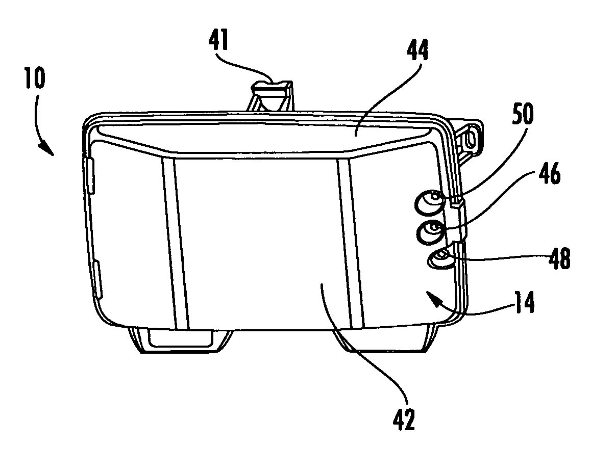
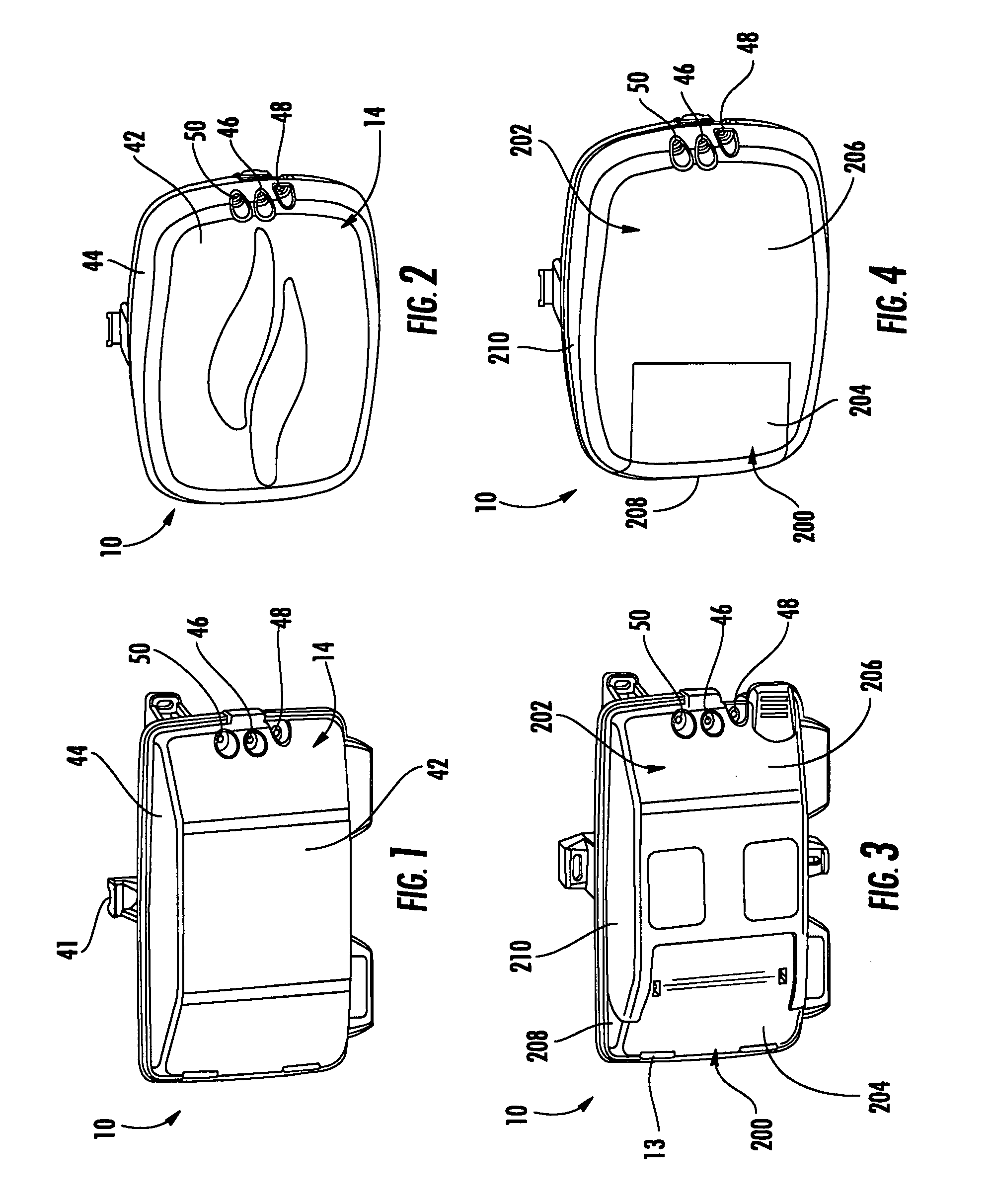
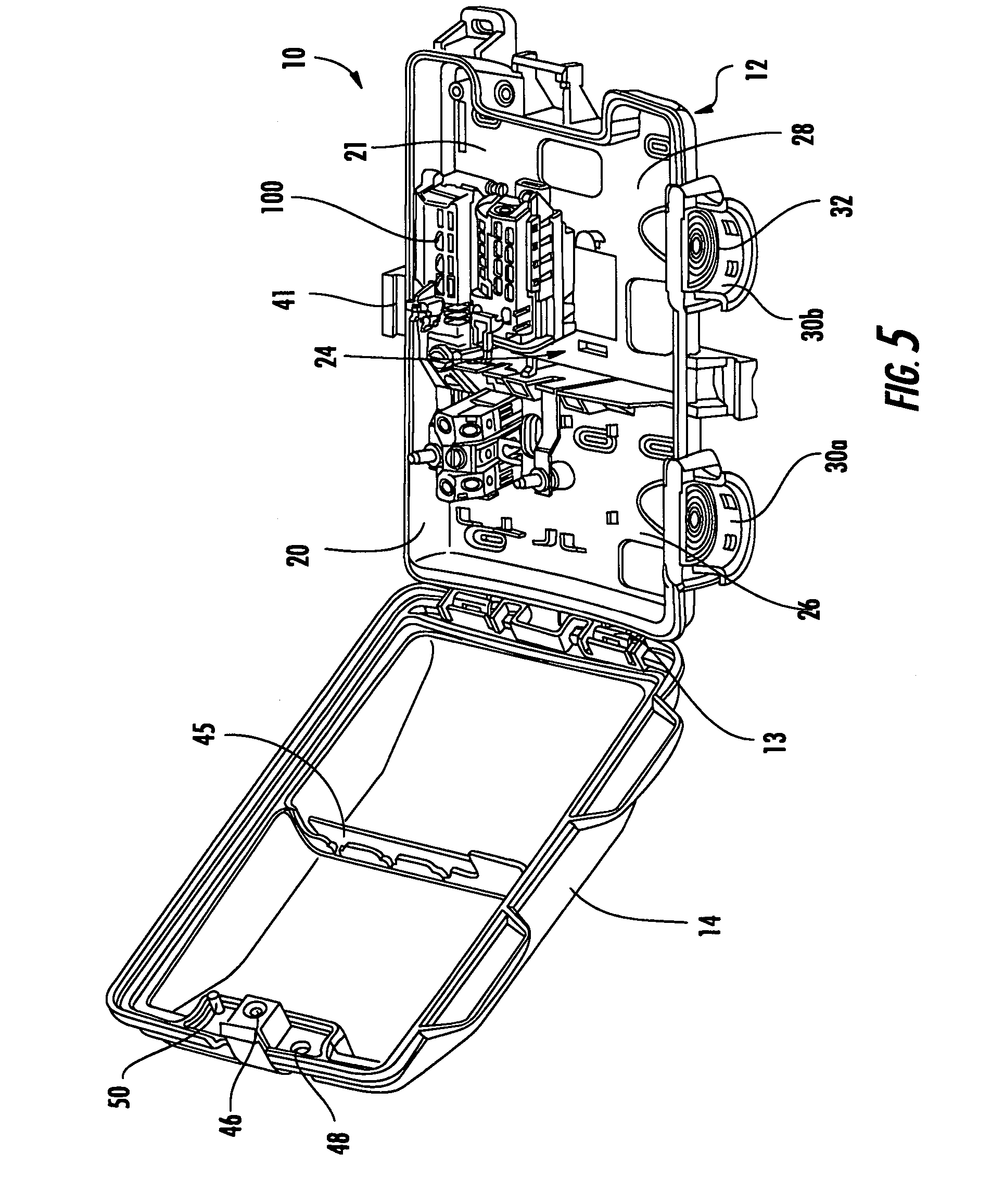
[0082] Reference will now be made in detail to several exemplary embodiments of the invention, and examples of which are illustrated in the accompanying drawings. Whenever possible, the same reference numerals will be used throughout the drawings to refer to the same or like parts. Various embodiments of a universal network interface device are shown throughout the figures and are designated generally by reference number 10.

[0083] Throughout this description, positional terms, such as left, right, top, bottom, front, rear, side, etc., and relative terms, such as larger, smaller, nearer, farther, etc., are utilized herein for purposes of explanation only, and as such, should not be construed as limiting the scope of the invention or the appended claims in any manner. In the embodiments shown, the universal network interface device 10 is capable of accommodating various examples of line modules and protectors now known or hereafter devised. The network interface devices shown and des...


PUM


Abstract

A line module includes a plurality of pivoting insulation displacement connector holders, an insulation displacement connector (IDC) positionable in at least one holder when the holder is in a connected position, and a gel-less jack in electrical communication with at least one IDC.

Description

BACKGROUND OF THE INVENTION [0001] 1. Field of the Invention [0002] The present invention relates generally to a network interface device used in a telecommunications network, and more specifically, to a universal network interface device capable of accommodating conventional line modules and protectors and including independent subscriber and telecommunications service provider access. More generally, the present invention relates to telecommunications and, more particularly, to equipment useful at subscriber demarcation points. [0003] 2. Technical Background [0004] Telephone service is provided by a telephone company (“provider”) to a number of different customers of the provider, commonly referred to as “subscribers.” Each subscriber may purchase as many separate telephone lines as desired and equip his or her home or business with various types of telephone equipment. Subscribers are responsible for proper operation of the telephone equipment and the provider is responsible for ...

Claims


Application Information

Patent Timeline
IPC IPC(8): H04M1/00H04M9/00
CPCH01R4/2433H01R2201/16H04M1/0293H04Q1/023H04Q1/114H04Q1/116H04Q1/021H04Q1/028
Inventor VO, CHANH C.TENHOLDER, RODGER A.NAPIORKOWSKI, JOHN J.
Owner CORNING OPTICAL COMM LLC
Why Eureka
Try Eureka