Mechanical broadhead with expandable blades

a broadhead and expandable technology, applied in the field of mechanical broadheads, can solve the problems of blade cracking upon hitting the target, blades not working properly, and faster kill of the target animal, so as to improve the flight of arrows, reduce the stress of blades, and improve the effect of cutting design

Active Publication Date: 2007-07-12
RAMCAT LLC
View PDF83 Cites 35 Cited by
  • Summary
  • Abstract
  • Description
  • Claims
  • Application Information

AI Technical Summary

Benefits of technology

[0017] The current invention reduces stress on the blades, provides an improved cutting design, and has a geometrically unique design for the front tip, front body, broadhead body, cutting blades, and retaining springs to work together. The design of this invention, specifically the geometry of the blade angle and the out

Problems solved by technology

Also, as the blades are extended, the intention is to cut a hole that will lead to hemorrhaging, resulting in a faster kill of the target animal.
Some of the past designs have put much stress on the blades, which posed the threat that the bl

Method used


Image

  • Mechanical broadhead with expandable blades
  • Mechanical broadhead with expandable blades
  • Mechanical broadhead with expandable blades

Examples


first embodiment

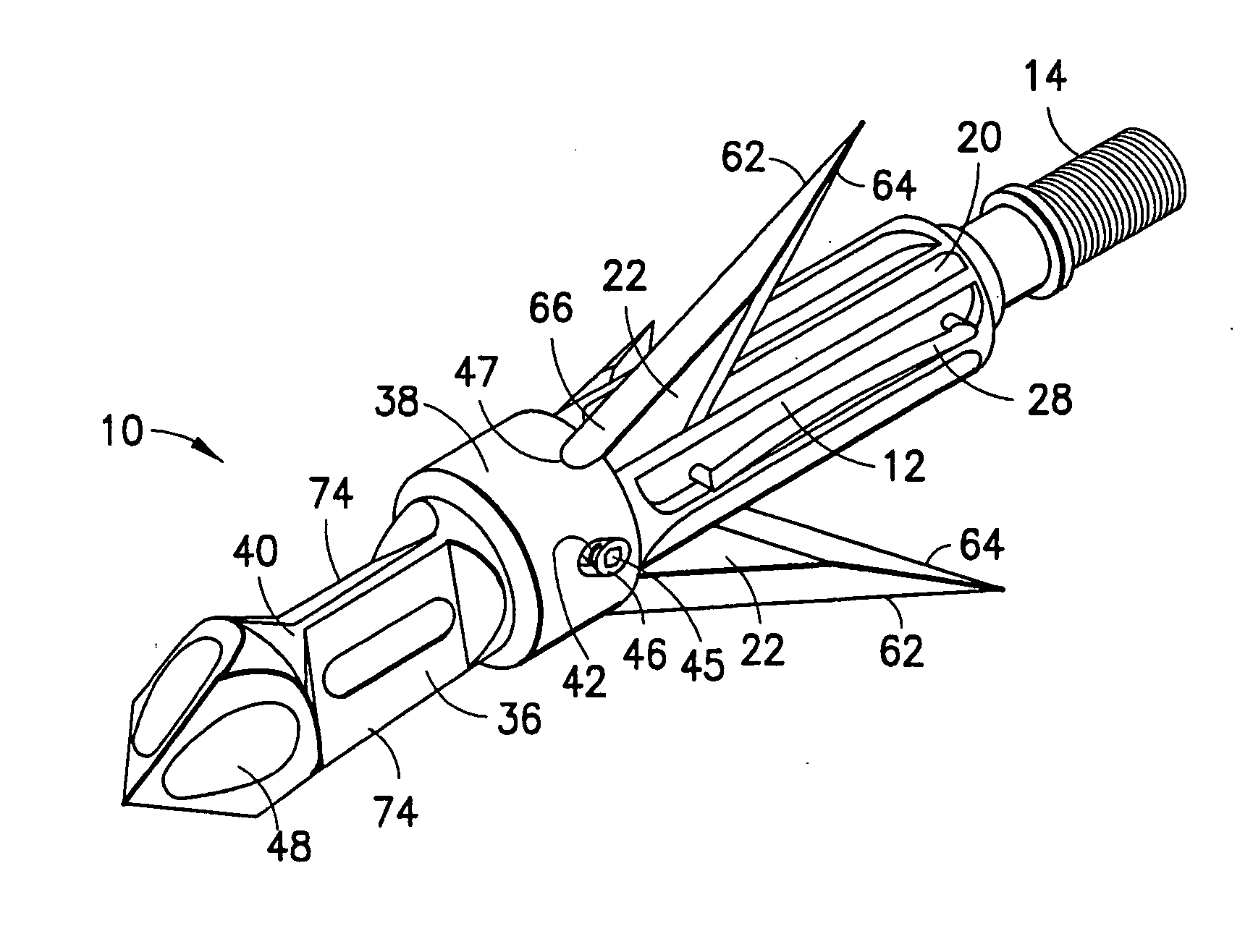
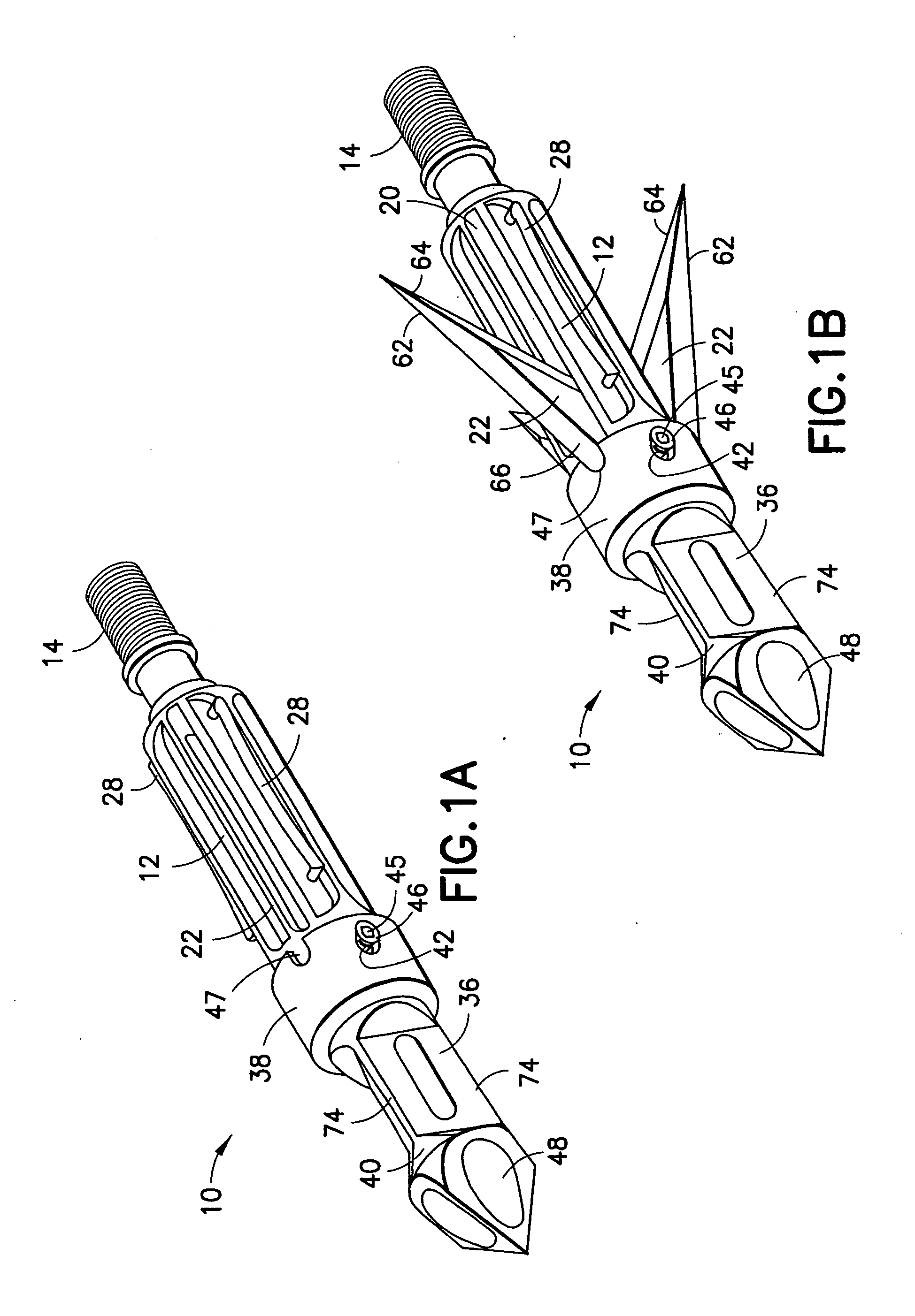
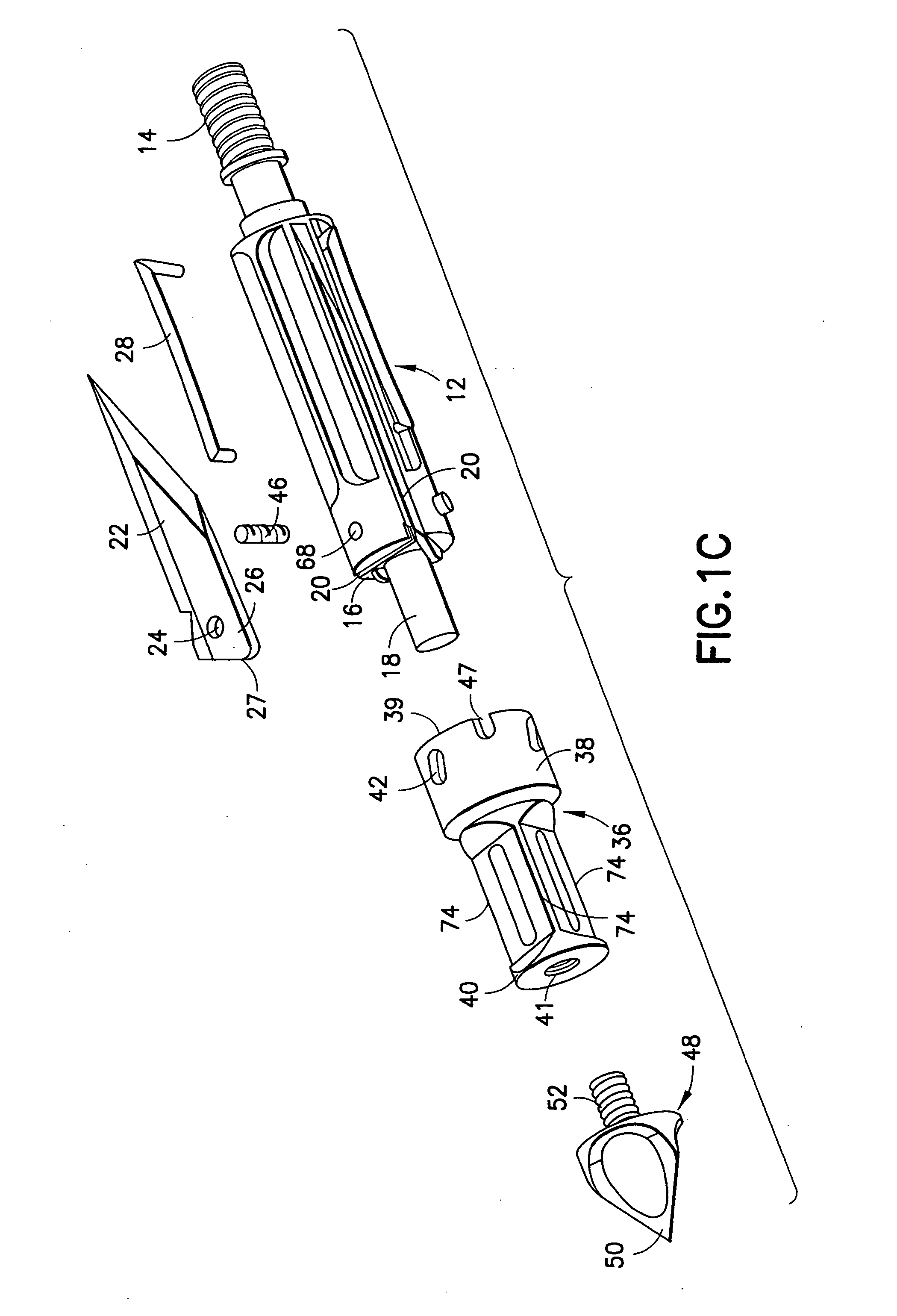
[0042] As shown in FIGS. 1A-1C and particularly in FIGS. 4A-4H, the front tip 48, comprises a sharp three-sided chisel point 50 containing a threaded shaft 52 that is removably secured within a threaded opening 41 of the frontal end 40 of the front body 36. This chisel point 50 can be formed from stainless steel, titanium or any other known material having sufficient strength characteristics to obtain efficient penetration into the target and create sufficient front-end load which enables broadhead deployment. Preferably, chisel point 50 includes balled out portions 76. These balled out portions 76 may be formed, for example, by the application of ball mills into the tip 48. These balled out portions 76 form a “shelf”78 which is at an approximate 90 degree angle behind the point 50 to increase the front end load of the broadhead 10 upon contact with the target and allow for a deeper penetration of the broadhead 10 into the target. This is achieved because, upon impact with the targ...

second embodiment

[0043] as shown in FIG. 7, the front tip 48 may comprise a cut-from-the-start razor tip or a two-sided razor 54 containing a threaded shaft that is removably secured to the front body 36. In this embodiment, the razor 54 may be enclosed within a cone-shaped sacrificial plastic sleeve 56 wherein the plastic sleeve 56 breaks off upon contact with the target.

[0044] The broadhead 10 of the present invention may be reset by simply inserting a sharp object, such as a knife tip, under the front end 30 of the retaining spring 28 and using a screwdriver twisting type motion, as depicted by arrow “C” in FIG. 6. This twisting motion will allow the spring 28 to slide out from behind the blade 22 allowing it to retract back into the broadhead body 12 and into the loaded position. The tip of the front end 30 of the spring enters through the front hole 70 of the broadhead body 12 to contact the side of the blade 22. This front end tip of the spring applies a frictional force to the blade 22 to ma...


PUM


Abstract

A mechanical broadhead for attachment to an arrow having a broadhead body including a plurality of blade windows formed therein, a geometrically angled retractable blade attached within each of the blade windows, retaining springs for retaining the blades in a retracted position during flight, a front body slidably mounted onto the broadhead body, and a front tip secured to the front body. Upon contact with a target, the front tip and front body slide rearwardly into an end of the geometrically angled blades, thus pushing each of the blades through the blade windows into a deployed position. The blades of the broadhead are reset by inserting a sharp point underneath an end portion of the retaining springs and applying a slight twisting motion allowing the blades to retract back into the broadhead body into a loaded position.

Description

CROSS REFERENCE TO RELATED APPLICATION [0001] The present application claims priority to U.S. Provisional Application Ser. No. 60 / 756,971 filed Jan. 6, 2006.BACKGROUND OF THE INVENTION [0002] 1. Field of the Invention [0003] The present invention relates generally to a mechanical broadhead for attachment to an arrow and, in particular, to a mechanical broadhead that has blades which are retracted into the body of the broadhead during flight and open upon impact with the target. [0004] 2. Description of Related Art [0005] Previously designed mechanical broadheads that are well-known in the art were constructed to lessen the wind effects on the arrow and to provide a wounding shot that would kill the animal more quickly. There have been various designs that enable the blades to be held in during flight and to expand outward upon impact. The retractable blades in various prior art designs enable the arrow to fly straighter than a fixed blade broadhead because of the elimination of the ...

Claims


Application Information

Patent Timeline
IPC IPC(8): A63B65/02
CPCF42B6/08
Inventor FULTON, BRETT
Owner RAMCAT LLC
Why Eureka
Try Eureka