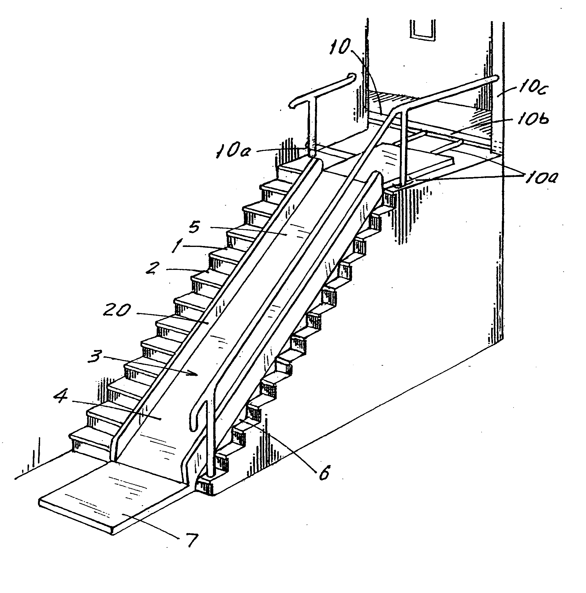
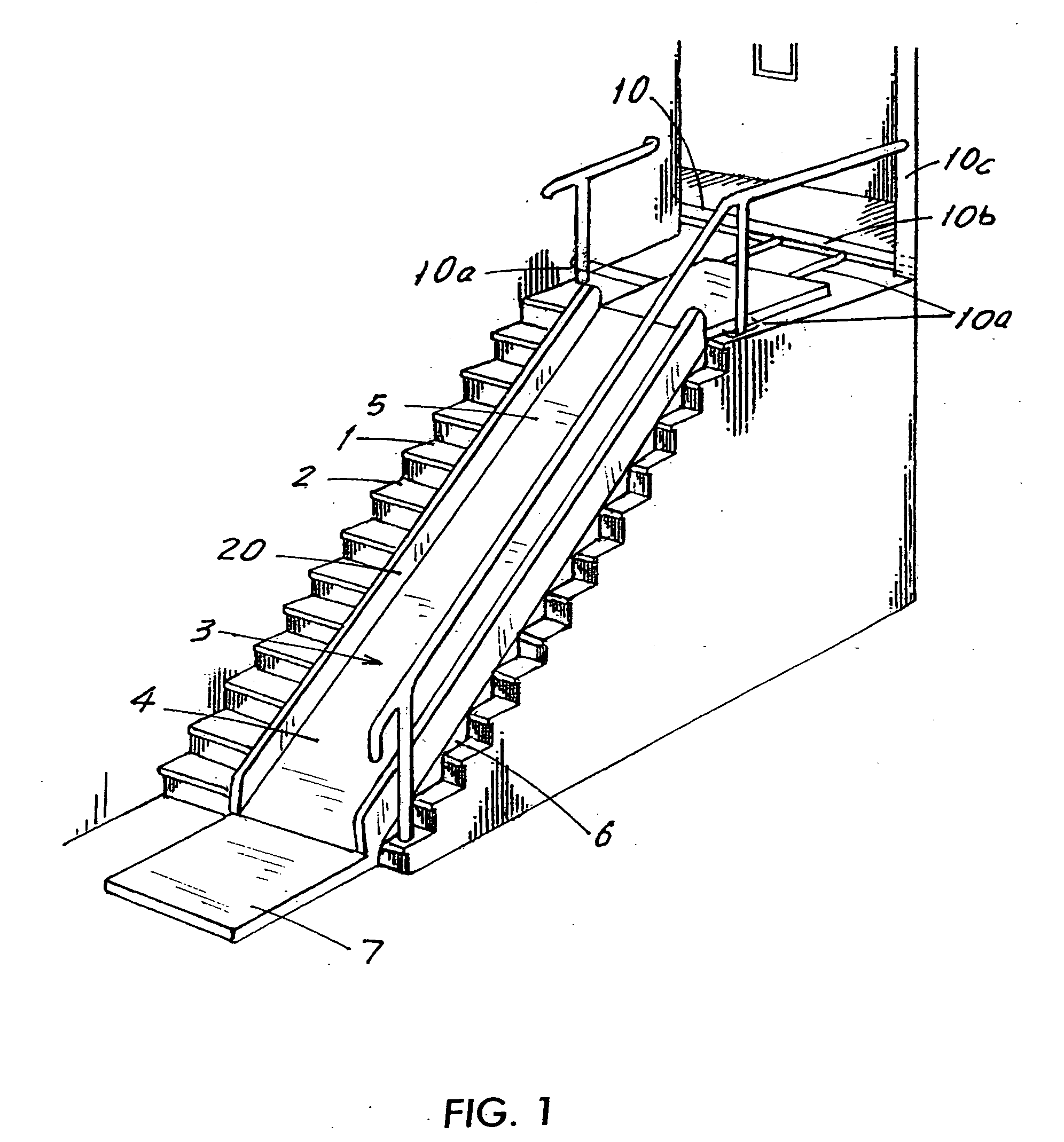
[0024]FIG. 1 schematically shows the side view of a stairway 1 having a number of steps 2. The inventive slide 3 has a longitudinally extending inflatable body 4. The body can be made of any suitable material such as vinyl or rubber. The body 4 has a smooth, generally flat upper section with a surface 5 along which a user can slide when the body 4 is inflated, preferably protected by inflatable sidewalls 20 to prevent bumping into the walls or steps of the staircase. The body 4 also has a lower section 6 with a stepped configuration whereby the lower section supports the upper section 5 on the steps 2 of the stairway 1 when the body 4 is inflated.
[0025] At the bottom of the body 4 is a landing portion 7, with an optional inflatable protective wall 8 (FIG. 2) which preferably encloses the landing area 7. The body 4 can be made up of a single chamber or a plurality of inflatable chambers that are sealed from one another to improve structural rigidity and enable continued use even if one of the chambers has sprung a leak. The chambers can include a sliding chamber 22 (or several such chambers), step chambers 24a, 24b, etc., expansion chambers 9, a landing chamber 7a, side wall chambers, and so on. See FIG. 3.
[0026] The interiors of the various chambers may include internally secured straps 6a, extending between opposed wall surfaces. The straps 6a are made of non-stretchable, thin material, e.g., lightweight cloth, and serve the purpose of defining the ultimate shape of the slide when fully inflated and preventing any weaker section from over-expanding, without meaningfully increasing the weight of the stowed, deflated slide.
[0027] As previously stated, the bottom section of the slide 3 is configured to provide supports that rest on the steps when the slide is inflated. Since steps are not always uniform in height, one or more of the horizontal portions of the lower surface 6 of the slide can be provided with separate expansion inflatable expansion chambers 9 which can be inflated to fill a gap between the lower surface 6 and the top of a step. Further, step chambers 24a, 24b may be longitudinally shorter than the steps and end at vertical surface 24c.
[0028] The upper end of the slide 3 is provided with an arrangement 10 (FIG. 1) for supporting the slide at the top of the stairway. The supporting structure 10 can have various constructions. For example, in a simple form, ropes 10a could be provided that are attached to grommets at the top end of the slide and the ropes are then tied off, for example, to the railing or a heavy piece of furniture at the top of the stair or to U-shaped brackets (not shown) that can be fastened securely to grip the door posts at the top of the staircase. Alternatively, the mounting arrangement 10 can be a bar 10b attached to the upper end of the slide and having a length so that the bar engages behind a railing or the staircase doorposts 10c to support the slide. Various other types of support arrangements can also be used and are all intended to fall within the present invention even if not specifically described here.
[0029] The slide may be as wide as the staircase. But, as shown in FIG. 1, the slide may have a width so as to leave a portion of the stairway exposed to allow users to climb up the steps 2.
[0030] The slide 3 can be inflated in a number of different ways. The simplest manner is by providing at least one closeable inlet 15 (FIG. 3) through which air can be provided by either manual blowing or a pump 16. In another embodiment (FIG. 4), pump 16 and manifold system 13 is provided. In this embodiment, many of the steps have an air inlet 12 that is connected to a manifold 13 which is in turn connected to the pump 16. The manifold 13 can be made of a flexible tubing. Alternatively, the manifold may be incorporated within the outermost stair of the slide or may be located along the bottom surface of the slide. When the pump is actuated, air passes through the manifold 13 into the inlets 12 to inflate the slide 3. The manifold preferably includes air conduits for the slide body 22 via an inlet 12a, for the landing 7 via inlet 12b, for the sidewalls via inlet 12c, and so on. Once an appropriate pressure is achieved in the slide to properly inflate the slide, the pump 16 can be turned off.
[0031] It is also possible to provide a pressure sensor 15 at one or more of the inlets. This pressure sensor can be electrically connected to the pump 16 so as to turn the pump off when a specific pressure is present in the slide and also to turn the pump on if the pressure in the slide falls below a specified level.
[0032] For deflating the slide, it is possible to reverse the pump which will cause the air in the slide to be sucked out via the openings 12, 12a, 12b, etc. and the manifold 13, to allow the entire slide 3 to be quickly folded up into a very small package. An alternative would be to simply disconnect the manifold 13 from the openings 12 to let the air in the slide to escape. The manifold 13 can be connected by conventional quick-connect couplings. When deflated, the body can be folded or rolled up into a small package that is easily storable, for example, in a closet.
[0033] It is also desirable to allow the pump to be remote controlled so that a user of the slide or someone else, e.g., the owner, can control inflation of the slide via remote control 16a.
[0034] When using a pump attached by a manifold to the slide for inflation purposes, it is possible to provide a plurality of small pin-holes 17 (shown in exaggerated size in FIG. 2) in the upper surface 5 so that a small quantity of air can escape from the slide to create an air cushion which will provide less friction to a person or a chair or cushion (to be described) sliding down or up the slide.
[0035] If the width of the slide is substantially equal to the width of the steps (FIG. 2) so that it is not possible to walk up the steps next to the slide, straps or handles 18 are mounted to the slide so that the handles can be grasped by a child to assist in climbing up the slide from bottom to top. The strap 18 can be of any desired material suitable for the purpose. The slide is provided with reinforcement in the areas where the handle 18 are attached so as to prevent tearing or damage to the slide when the handles are used for climbing. Such straps may also be provided at the sides and used to tie the slide to a stair railing for increased support of the slide.
[0036] The slide 3 can be used as is to slide down various heavy objects, weighing as much as two or three hundred pounds or more, or for the enjoyment and entertainment of children. However, by providing a winch mechanism 19 (FIG. 4) and a seat 18 with a harness 34, it is possible to utilize the slide as a means for invalids or disabled persons to travel up and down a stairway, they normally would not be able to negotiate. The present invention is thus an inexpensive alternative to costly in-home elevators and stairway elevators, that must be professionally installed. The winch system 19 can be anchored or secured to the floor or the door posts or railing or wall at the top of the staircase by any of the widely known means and implements to secure structures to immovable objects, e.g., bolts, screws, ropes, brackets, etc. For example, the main winch 19 may be secured to a wall 31 with winching ropes 19a guided and supported on rotatable stand 19b being attached to the chair 18 to pull up or allow the chair 18 to slide down. The ropes may also be designed to keep the chair stable on the slide.
[0037] The seat 18 may be formed as an inflatable seat 30 (FIG. 5) with an (inflatable) body 32, harness 34, and arm rest 36. The (inflatable) bottom portion 38 is wedge shaped and has a sliding surface 44 angled to approximate the pitch of the steps. The sliding surface can be made of a solid board, e.g., wood, metal, plastic, and have perforations 33. When the board 44 is perforated, the chamber 38 remains connected to the pump line to blow air out to reduce sliding friction. The chair 18 may be dragged over any floor beyond the slide, to get an invalid to a bedroom, a bathroom or the like, preferably by flattening the wedge 38. The slide may define channels at its sidewalls in which the bottom portion 38 of the chair is wedged, to solidly hold the chair and prevent its tipping or falling off the slide surface
[0038] Alternatively, the chair may be a relatively flat cushion 58 with a seat 60 and a housing with hooks 62a, 62b by which it is attachable to the ropes 19a of the winch mechanism 19. As another alternative, the person may don a separately provided body harness having a back attachable to the rope of the winching mechanism 19 so as to pull up or allow controlled down sliding of the person, without using a sliding chair or cushion. The instant inventors perceive the means—whether a chair, a cushion or a harness—to be interchangeable.
[0039] To proceed down the slide, a person merely needs to sit in the seat 18 and don the harness 34 so that the person does not fall out of the seat. If the pump 19 is equipped with a remote control as discussed previously, it is not even necessary to have the slide inflated prior to use by the person. Once seated in the seat 18, the pump can be activated to inflate the slide. Once inflated, the seat can be lowered down the slide by a handheld pulley with an appropriate mechanical advantage and/or via the winch mechanism 19. The bottom of the seat 18 can be sloped so that the seat remains horizontal while sliding down the slide. The chair may be configured so that the person resting on it faces down or, alternatively, sideways.
[0040] To start the sliding chair down the inclined surface, the frail invalid or incapacitated person may sit down on the chair or cushion at the location of the first step and then operate the winching mechanism to which the chair is fastened. Alternatively, the inflatable slide surface may start at a top landing, where the slide has a horizontal section and the person may sit down on the chair at that horizontal level. Operating one of the controls will inflate the distal end of the landing to, in effect, urge the chair forward to allow the person to start sliding down by gravity, held back by the winch. Alternatively, the bottom chamber 38 is tethered to the pump 16 and the chamber 38 is inflated only when the chair is positioned over the steps. Although the invention shows the chair with the person facing in a direction of travel, the person may be sitting at the 90° position, able to see up the stairs by facing left or down the steps by facing right.
[0041] The body 4 of the slide 3 may be constructed such that the height of the sliding surface above the steps is on the order of 2-3 feet, i.e., sitting height, so that a person may sit on a relatively flat cushion with the feet dangling above and not quite reaching the level of the steps.
[0042] A major advantage of the present invention is the low weight and size of the deflated overall system. Deflating the sliding body reduces its weight and volume so considerably, that it allows an elderly companion of a person or the elderly person himself or herself to both deploy the slide and to disassemble and store it away. The system can be taken with a person who needs to use it at someone else's home and easily deployed there. The slide can also be deployed on stairs at public buildings, etc.
[0043] Moreover, the system of the present invention can also be utilized in homes for ferrying heavy objects up and down a staircase, and for this purpose, instead of a sliding chair, a sliding container is provided in which heavy objects can be placed and the objects themselves tied to the winching rope and so conveyed up or down stairs. Persons in the moving business may quickly deploy it to slide or lift refrigerators, washing machines, etc. over stairs as noted.
[0044] The system of the present invention can be provided in a form where the step shaped pieces are not inflated (or not provided) and the slide is disposed over flat surfaces to allow horizontal sliding of heavy objects therealong. The sliding system of the present invention can be provided in several attachable sections 66a, 66b and 66c attached by straps 68 (FIG. 6), so that it can accommodate different staircase lengths or distances over which heavy objects or people must be ferried.
[0045] The sections can be attached to each other by strings 68, ropes, snaps, adhesives or any known means. Moreover, the sections need not be longitudinally straight, and may be somewhat arcuate so several sections can be joined to fit an arcuate staircase.
[0046] A main aspect of the present invention is that the material of the slide be sturdy enough not to easily rupture and, at the same time, very light. Moreover, either the chair or the container in which objects can be placed have bottoms that similarly have very low friction coefficients, so there is little friction between the two sliding surfaces, whereas either a person or a heavy object can be easily slid or pulled down or pulled up or slid down along the sliding surface.
[0047] Although the present invention has been described in relation to particular embodiments thereof, many other variations and modifications and other uses will become apparent to those skilled in the art. It is preferred, therefore, that the present invention be limited not by the specific disclosure herein.