Gas gun having pressure driving device

a driving device and gas gun technology, applied in the field of compressed gas guns, can solve the problems of increasing manufacturing costs, and achieve the effect of reducing the manufacturing cost of compressed gas guns and simplifying the manufacturing process of compressed gas guns

Inactive Publication Date: 2007-07-19
GAN YIAUGUO
View PDF16 Cites 8 Cited by
  • Summary
  • Abstract
  • Description
  • Claims
  • Application Information

AI Technical Summary

Benefits of technology

[0008] The primary objective of the present invention is to provide a compressed gas gun including a simplified pneumatic or pressure drivi...

Problems solved by technology

However, the loading bolt and the hammer and the control device form a rather complicated configuration ...

Method used


Image

  • Gas gun having pressure driving device
  • Gas gun having pressure driving device
  • Gas gun having pressure driving device

Examples


Embodiment Construction

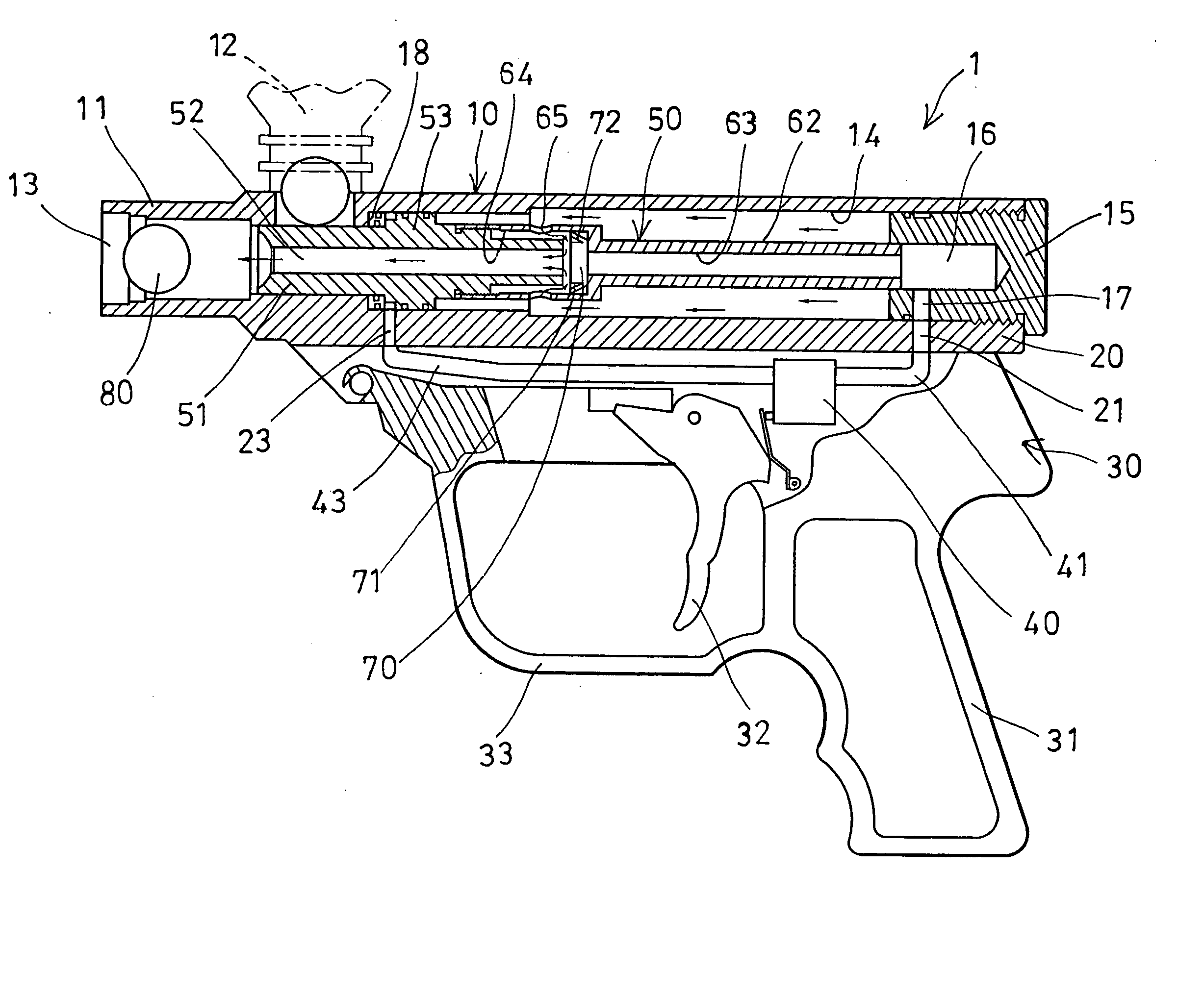
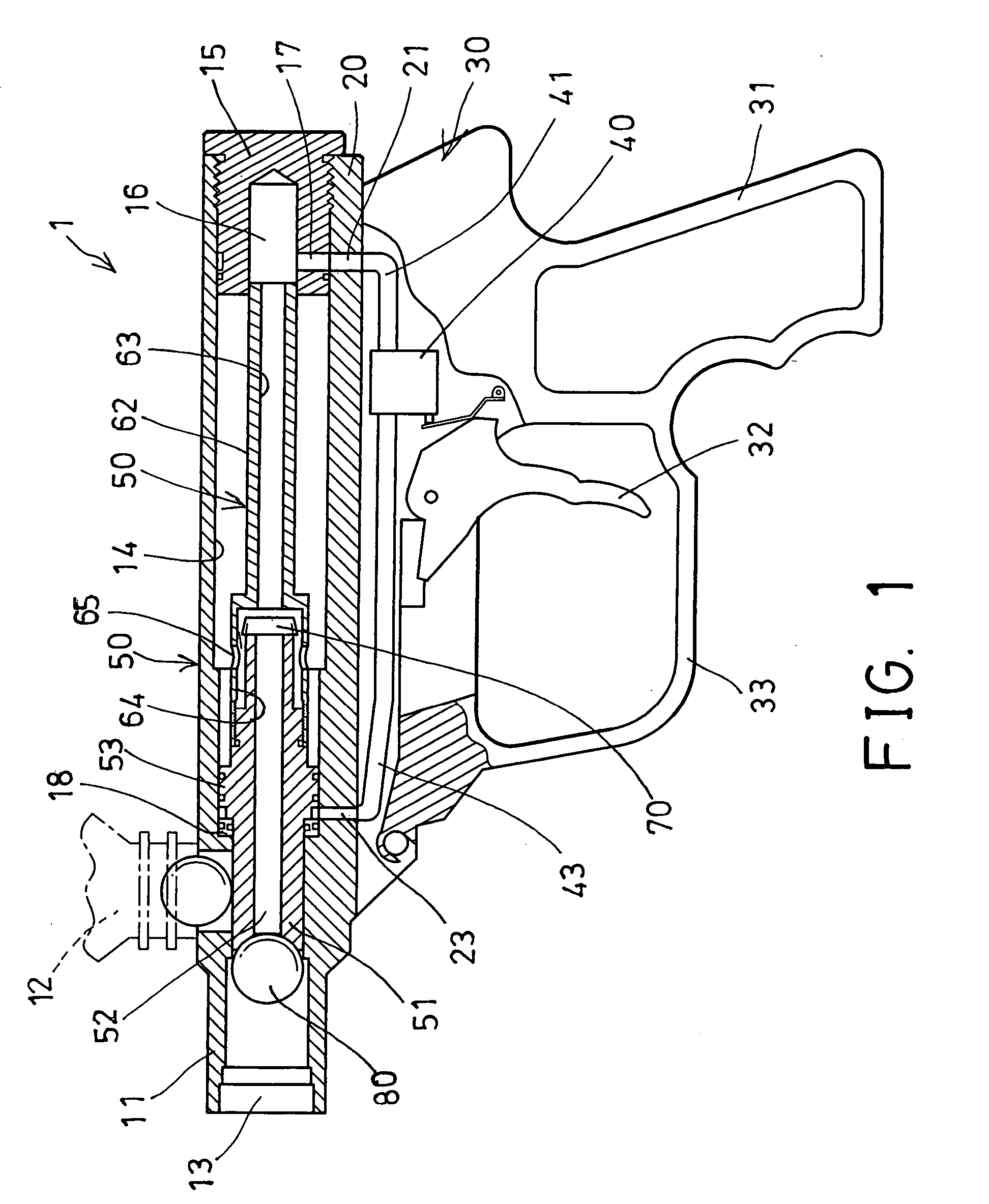
[0022] Referring to the drawings, and initially to FIGS. 1-2, a compressed gas gun 1 in accordance with the present invention comprises an upper housing 10, and a lower housing 30 having a hand grip 31 extended downwardly therefrom for being grasped or held by the users. The upper housing 10 includes a barrel 11 provided or extended forwardly therefrom, and a projectile feed tube 12 attached to the barrel 11 and opened into the barrel 11 for feeding or supplying projectiles 80 into a bore 13 of the barrel 11 one at a time. The bore 13 may be formed in the barrel 11 and / or in the upper housing 10.

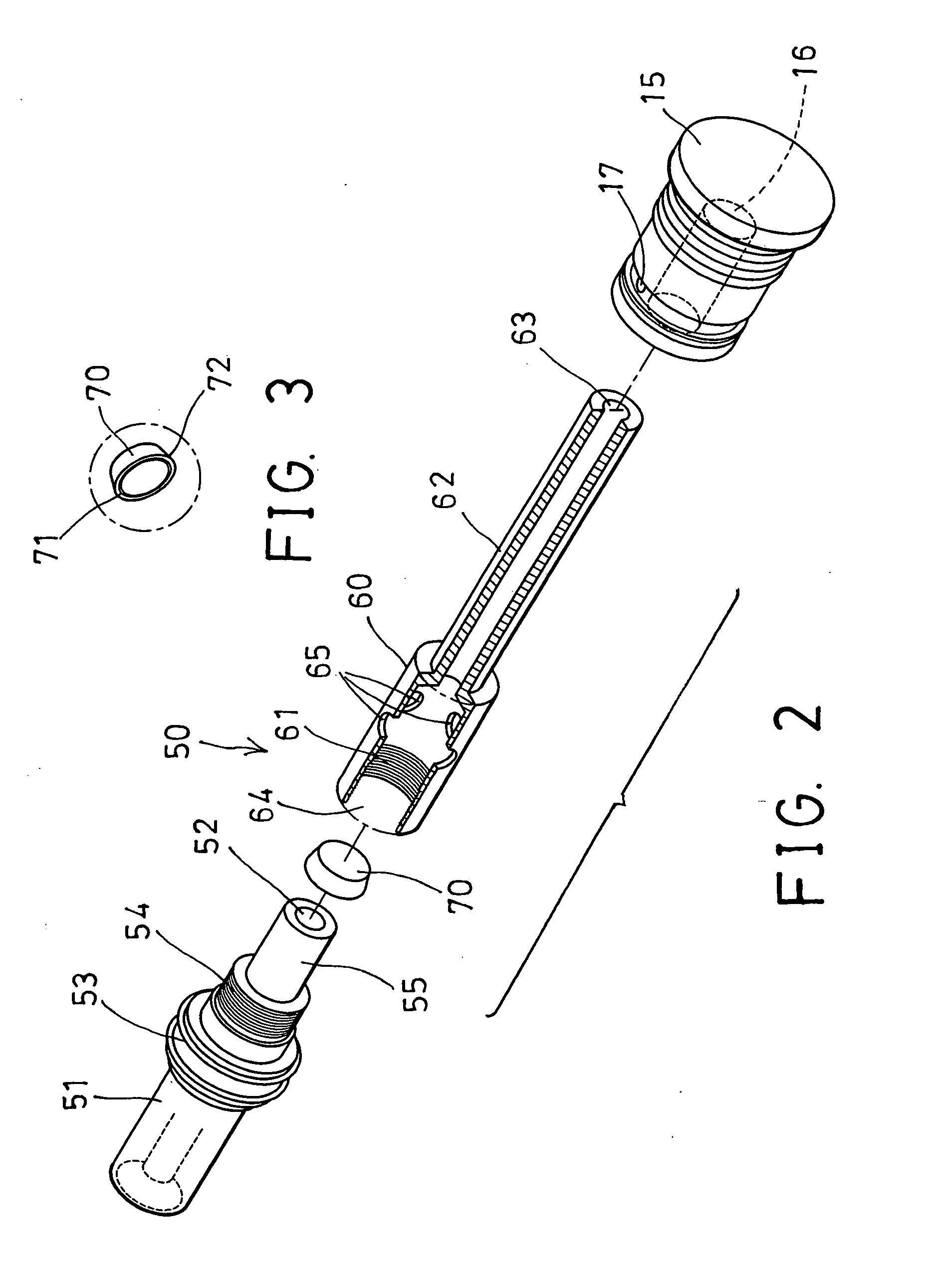
[0023] A loading device 50 includes a loading bolt 51 slidably disposed or engaged in the upper housing 10 or in the bore 13 of the barrel 11, and movable to engage with the projectile 80 that is supplied or fed into the barrel 11 (FIGS. 1, 4) and for feeding or loading the projectile 80 forwardly toward a firing position (FIG. 4). The loading bolt 51 includes a passage 52 formed therein an...


PUM


Abstract

A compressed gas gun includes an upper housing having a barrel for receiving projectiles to be fired and having a high pressure storage chamber, a loading bolt slidably engaged in the upper housing and movable to feed the projectile forward to a firing position. A pipe is attached to the loading bolt and includes an inner space, a conduit having a pathway, and one or more apertures for communicating the inner space with the barrel. An enclosing device may be used for selectively enclosing a passage of the loading bolt to allow the pressure gas to fill the pipe and the high pressure storage chamber of the barrel, and for selectively disengaging from the loading bolt and enclosing the conduit to allow the pressure gas to fire the projectile.

Description

BACKGROUND OF THE INVENTION [0001] 1. Field of the Invention [0002] The present invention relates to a compressed gas gun, and more particularly to a compressed gas gun having a simplified pneumatic or pressure driving system for simplifying the manufacturing processes of the compressed gas gun and for reducing the manufacturing cost of the compressed gas gun. [0003] 2. Description of the Prior Art [0004] Typical compressed gas guns comprise a projectile feed tube for supplying projectiles into a barrel of a gun body one at a time, and the projectiles are preferably spherical in form and contain a marking fluid therein, a loading bolt is slidably disposed in the rear portion of the barrel for engaging with the one projectile that is supplied or fed into the barrel and for feeding or loading the projectile slightly forwardly toward a firing position. [0005] For example, U.S. Pat. No. 6,371,099 to Lee discloses one of the typical gas powered guns or paint ball guns also comprising a l...

Claims


Application Information

Patent Timeline
IPC IPC(8): F41B11/00
CPCF41B11/62
Inventor GAN, YIAUGUO
Owner GAN YIAUGUO
Why Eureka
Try Eureka