Method for producing valve housings, and a valve housing

a valve housing and valve technology, applied in the direction of valve details, nuclear energy welding apparatus, applications, etc., can solve the problem of small amount of waste material, and achieve the effect of reducing the number of chucking operations and correspondingly reducing production tim

Active Publication Date: 2007-07-19
BEHR THERMOT TRONIK
View PDF10 Cites 16 Cited by
  • Summary
  • Abstract
  • Description
  • Claims
  • Application Information

AI Technical Summary

Benefits of technology

[0010] In a preferred embodiment, the receiving bore, as well as the inlet conduits and the outlet conduits, extend transversely in regard to the extrusion direction of the billet material. It is possible in this manner to provide inlet conduits, outlet conduits and the receiving bore in the billet material, which only subsequently is divided into individual valve housings. In this way, it is possible to considerably reduce the number of chucking operations for machining processes in the course of cutting the inlet conduits, the outlet conduits and the receiving bore, because of which the production time can be correspondingly reduced.

Problems solved by technology

The reshaping of a rib after the section constituting the valve housing has been cut off the billet material requires a relative small outlay and results in only a small amount of waste material.

Method used


Image

  • Method for producing valve housings, and a valve housing
  • Method for producing valve housings, and a valve housing
  • Method for producing valve housings, and a valve housing

Examples


Embodiment Construction

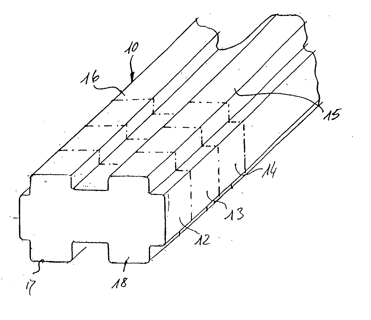
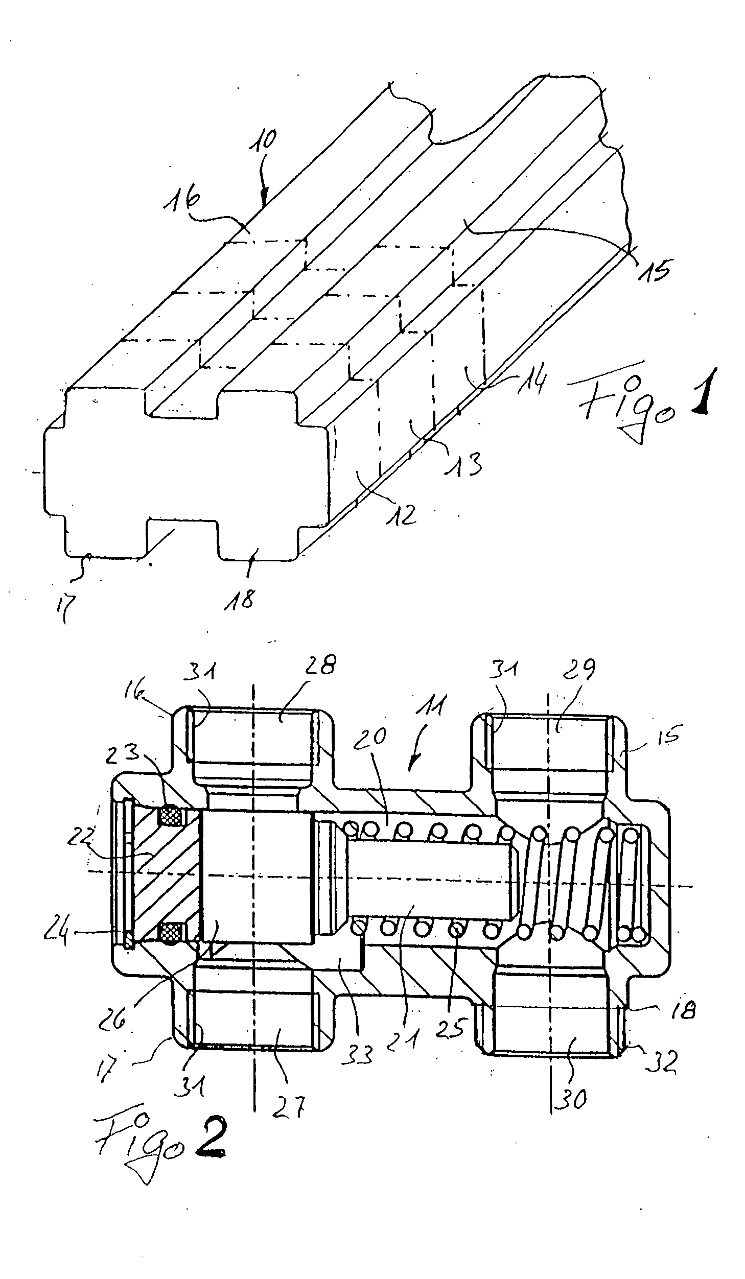
[0015] The profiled cast or extruded element 10 represented in FIG. 1 is used as the basic material for valve housings 11, such as shown in detail in FIG. 2. The profiled cast or extruded element 10, which is formed from a material suitable for these processes, is cut into individual sections 12, 13, 14, each of which is used as a valve housing.

[0016] The profiled element 10 has a parallelepiped base body, from the flat sides of which ribs 15, 16, 17, 18 protrude, which extend in the longitudinal direction (extrusion direction). In the exemplary embodiment, the profiled element 10 has an H-shaped cross section, in which pairs of the ribs 15, 18 and 16, 17 are located opposite each other. It is of course possible to provide a different arrangement of the ribs 15 to 18, in particular an arrangement in which the ribs are not located in pairs opposite each other, but are offset in respect to each other.

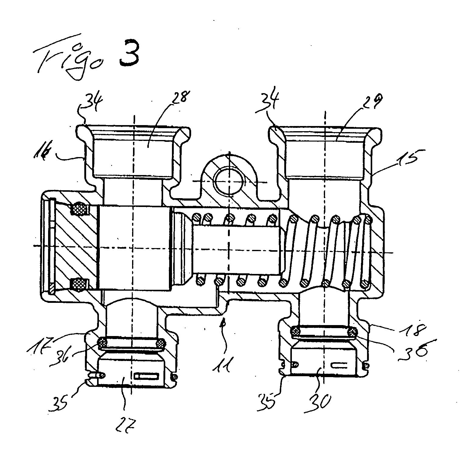
[0017] A receiving bore 20, which extends transversely in respect to the extrusion ...


PUM

PropertyMeasurementUnit
areaaaaaaaaaaa
temperatureaaaaaaaaaa
shapeaaaaaaaaaa

Abstract

In a valve housing 11, which is constituted by an section of an extruded billet material, into which are formed inlet and outlet conduits 27, 28, 29, 30, which are substantially arranged in a common plane, and a receiving bore 20 for at least one valve element 21, 26, arranged transversely in relation thereto, the billet material is formed as a profiled element provided with ribs 15, 16, 17, 18 which project from a substantially parallelepiped base body and in which ribs the inlet and outlet conduits 27, 28, 29, 30 open.

Description

CROSS-REFERENCES TO RELATED APPLICATIONS [0001] This application claims the benefit of German patent application 10 2006 003 259.4 filed Jan. 19, 2006, herein incorporated by reference. FIELD OF THE INVENTION [0002] The invention relates to a method for producing valve housings. More particularly, the invention relates to such a method performed by cutting sections off an extruded billet material and by working into the sections inlet and outlet conduits, which are substantially arranged in a common plane, and for producing a receiving bore, which extends transversely to the inlet conduits and is substantially arranged in a common plane, for at least one valve element. The invention further relates to a valve housing. BACKGROUND OF THE INVENTION [0003] It is known to arrange the valve corresponding to FIGS. 5 and 6 of U.S. Pat. No. 6,253,837 in a valve housing which was produced from a section of an extruded billet material. A receiving bore, which extends in the extruding direction...

Claims


Application Information

Patent Timeline
Patent Type & Authority Applications(United States)
IPC IPC(8): F16K27/00
CPCB21C23/142B21K1/24B23P13/04B23P15/001F16K27/0263F16K31/002Y10T29/49798Y10T29/49419Y10T29/49789Y10T29/49412Y10T29/49799Y10T29/49405Y10T29/49794F16K27/00F16K27/12
Inventor WILLERS, EIKEAUWEDER, ANDREAS
Owner BEHR THERMOT TRONIK
Why Eureka
Try Eureka