Vehicular headlamp

a headlamp and headlamp technology, applied in the field of headlamps, can solve the problems of difficult detection of the lamp center, inability to detect the head light testing apparatus, and inability to locate the lamp center, and achieve the effect of high level of precision

Inactive Publication Date: 2007-07-19
ZF FRIEDRICHSHAFEN AG +1
View PDF2 Cites 12 Cited by
  • Summary
  • Abstract
  • Description
  • Claims
  • Application Information

AI Technical Summary

Benefits of technology

[0009]Accordingly, it is an object of the present invention to provide a vehicular headlamp in which the headlamp is a multi light-source type lamp and a detection of the lamp center can be made with a high level of precision.
[0018]As seen from the above, in the present invention, the center mark that is provided on the headlamp; and by way of automatically detecting or visually recognizing the center mark and by way positioning and aligning the optical axis of an imaging device of a head light testing apparatus with the center mark, it is possible, even if the headlamp includes multiple light source units, to detect and locate, with a high level of precision, the center of the light emission area of one or more light source units that form the hot zone; and especially for a low-beam light distribution pattern, it is possible to detect and locate, with a high level of precision, an elbow point in the low-beam light distribution pattern. Thus, in the headlamp according to the present invention, accurate tests of light distribution patterns can be performed.

Problems solved by technology

In such a lamp that includes a plurality of light source units (called a “multi-light source type lamp”), it is difficult to detect the lamp center because a light beam is emitted from each of the plurality of light sources.
In other words, when a head light testing apparatus receives the light beams emitted from the multi-light-source type lamp, since the light beams are respectively received from the plurality of light source units, the head light testing apparatus is not able to judge which one of the light beams received from the light source units should be used to specify the lamp center of the lamp.
Even if a reflective part is provided at the center of the lens as in Japanese Utility Model Application Laid-Open (Kokai) No. 4-2401, it is not possible to detect or locate the lamp center as the center of the light distribution pattern, though it can detect the center position of the lamp.

Method used


Image

  • Vehicular headlamp
  • Vehicular headlamp
  • Vehicular headlamp

Examples


Embodiment Construction

[0030]Embodiments of the present invention will be described with reference to the accompanying drawings.

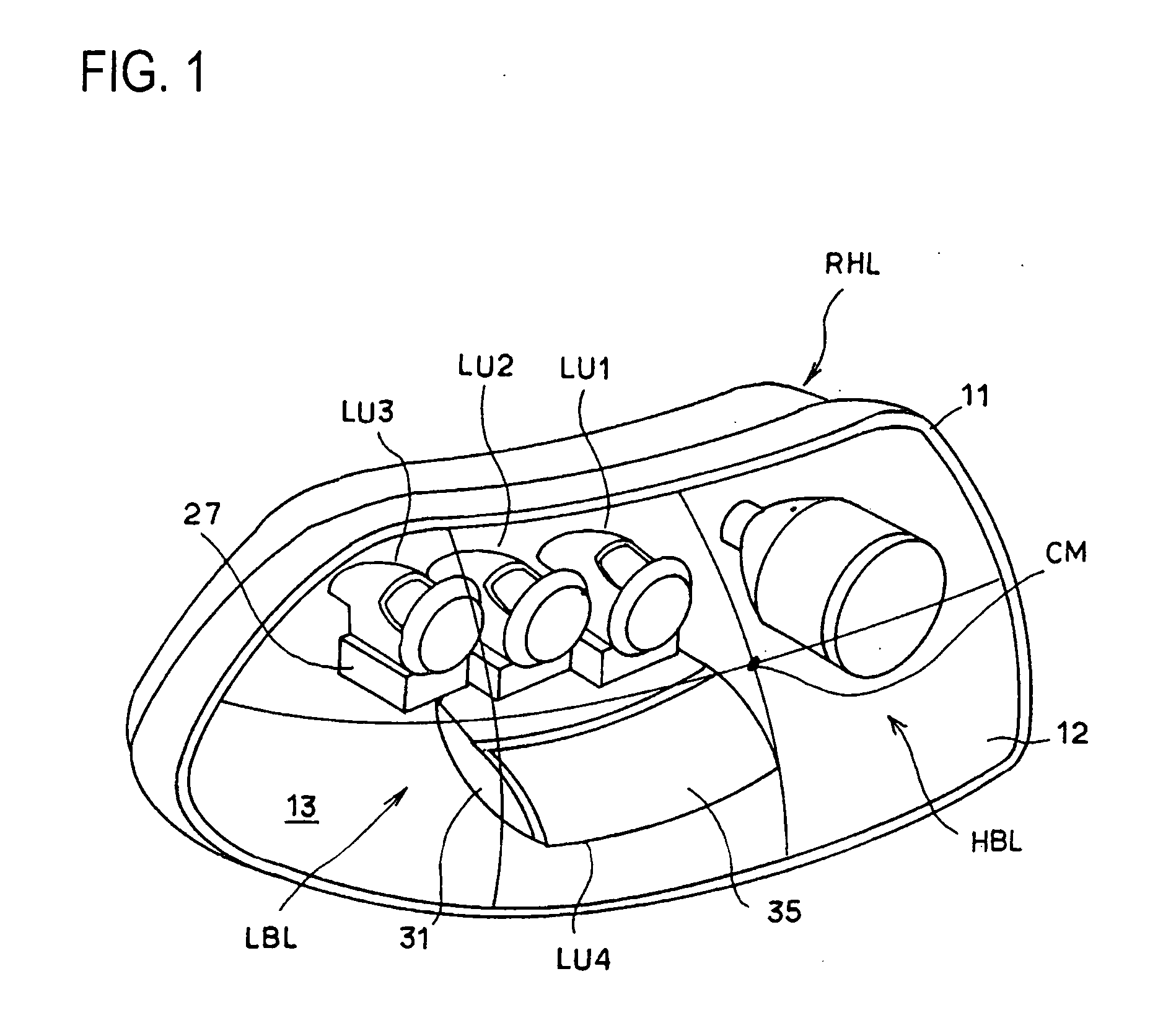
[0031]FIG. 1 shows the right-side headlamp RHL, which is one of the pair of headlamps HL (see FIG. 6) mounted on the left and right sides of the front part of an automobile to which the present invention is applied. The lamp chamber 13 of this headlamp is made up of, at least, a lamp body 11 and a transparent cover 12 attached to the front opening of the lamp body 11; and a high-beam lamp HBL and a low-beam lamp LBL are installed in this lamp chamber 13.

[0032]The high-beam lamp HBL is a single, projector-type lamp that uses a discharge bulb as its light source. Because such a projector-type lamp that uses a discharge bulb as the light source is already well known, a detailed explanation thereon will be omitted.

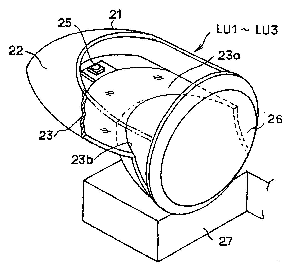
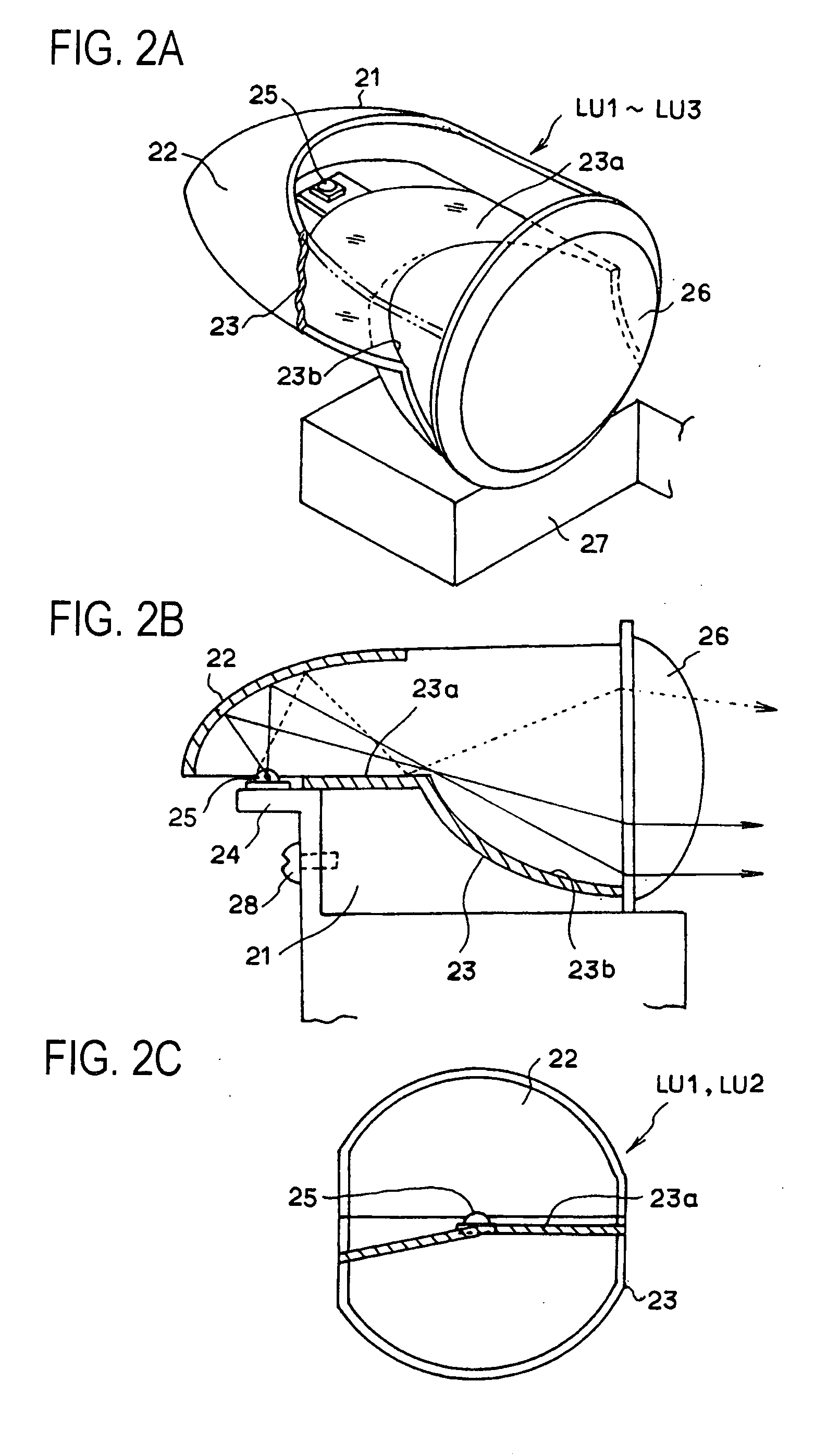
[0033]The low-beam lamp LBL is a multiple light-source type lamp that includes a plurality of light source units; and in the shown embodiment, the low-beam lamp LBL is comp...


PUM


Abstract

In a headlamp providing a predetermined light distribution pattern by combining illumination light beams that are respectively emitted from a plurality of light source units LU1 to LU4 each of which using a light emitting element as the light source, at least one of the plurality of light source units being a light source unit that forms a hot zone in the light distribution pattern, the lamp center being provided within a light emission area of the light source unit LU1 that forms the hot zone, and a center mark CM that indicates the lamp center being provided on the front cover of the lamp.

Description

BACKGROUND OF THE INVENTION[0001]1. Field of the Invention[0002]The present invention relates to a vehicular headlamp that includes a plurality of light source units and more particularly to a vehicular headlamp of which lamp center can be detected with a high level of precision.[0003]2. Description of the Related Art[0004]Headlamps for automobiles include a low-beam lamp in which the optical axis is directed downward so as to provide a predetermined light distribution pattern that prevents drivers in oncoming traffic from betting getting blinded. For such a low-beam lamp, a test called a head light test is performed using a head light testing apparatus. This head light test is to see if the low-beam lamp is directed toward a predetermined direction and to see if the low-beam lamp satisfies a predetermined light distribution pattern or not. In this test, it is necessary to detect a reference position for each lamp (called a “lamp center”) so that the lamp center is positioned and al...

Claims


Application Information

Patent Timeline
Patent Type & Authority Applications(United States)
IPC IPC(8): B60Q1/26
CPCF21S48/1159G01M11/064G01M11/062F21Y2101/02F21Y2115/10F21S41/151F21S41/148
Inventor ISHIDA, HIROYUKIYOSHIDA, SYOJIOKAWA, MASAO
Owner ZF FRIEDRICHSHAFEN AG
Why Eureka
Try Eureka