

Traveltime calculation in three dimensional transversely isotropic (3d tti) media by the fast marching method
- Summary
- Abstract
- Description
- Claims
- Application Information
AI Technical Summary
Benefits of technology
Problems solved by technology
Method used
Image

Examples
Embodiment Construction
[0024]Disclosed herein is a method for calculation of first arrival traveltimes in three-dimensional transversely isotropic (3D TTI) media that is based on the fast marching method. The method disclosed is comparatively more accurate than other prior art techniques. Further, the method provides advantages in that certain beneficial aspects of the fast marching method are not perturbed. For example, the method preserves computational efficiency and substantial stability for any 3D TTI velocity model applied to isotropic media, wherein the model includes large velocity gradients and arbitrary orientation of symmetry axis. In addition, the method disclosed can be advantageously applied to a Kirchhoff pre-stack depth migration for 3D TTI media and to estimate TTI parameters for Vertical Seismic Profiling (VSP) data.
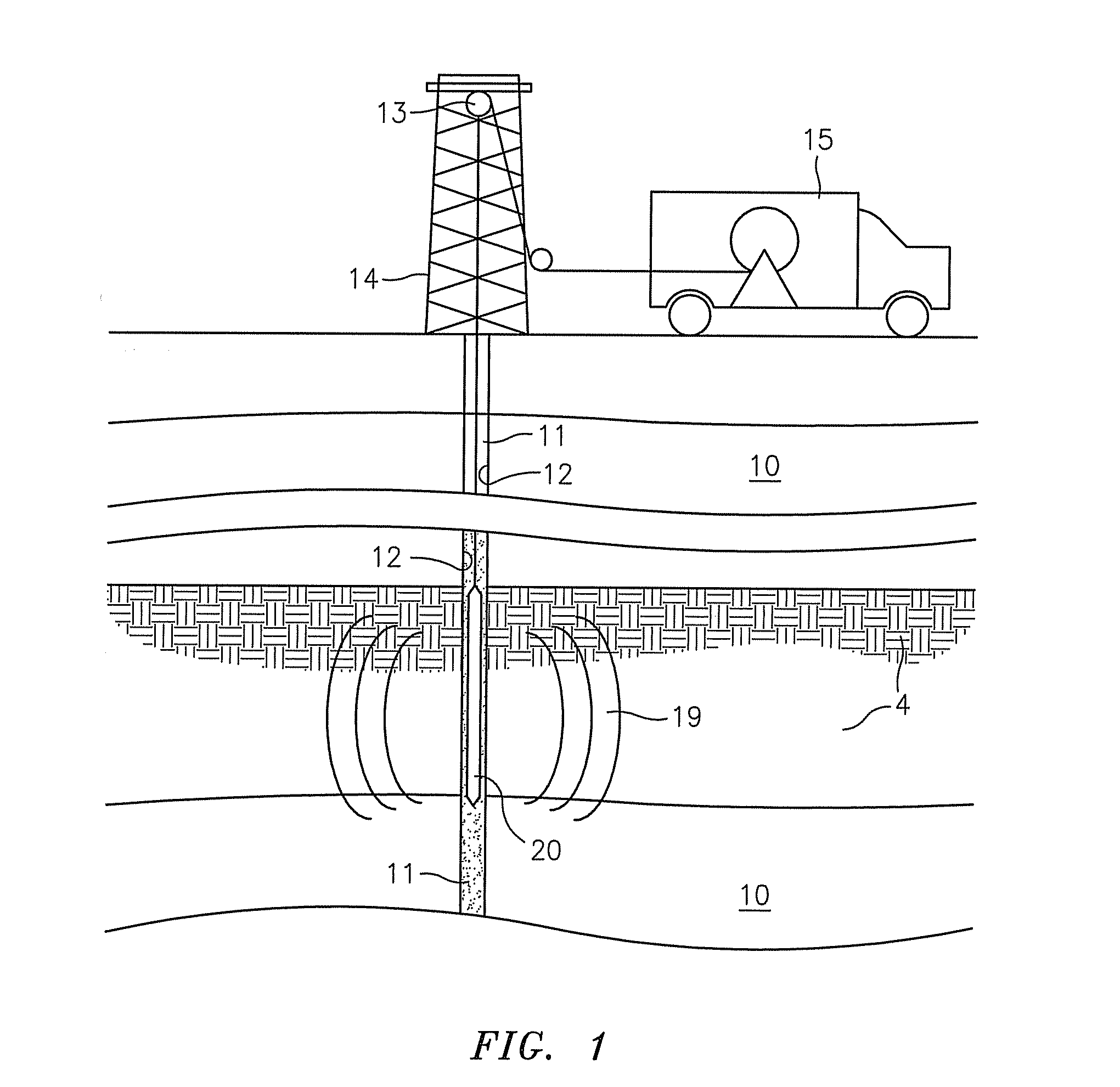
[0025]As depicted in FIG. 1, in typical embodiments, a tool 20 is disposed within a wellbore 11. The tool 20 is suspended by a wireline 12, typically from a derrick 14 using ...
PUM
 Abstract
Description
Claims
Application Information