Utility network engineering and design rules in three-dimensional models of utility networks

a utility network and engineering technology, applied in the field of computer software, can solve the problems of difficult to ensure that a given 3d model conforms to real-world design requirements, process can quickly become time-consuming and tedious, and subsequently changing or validating requirements is also difficul

Active Publication Date: 2007-07-19
AUTODESK INC
View PDF2 Cites 45 Cited by
  • Summary
  • Abstract
  • Description
  • Claims
  • Application Information

AI Technical Summary

Benefits of technology

[0015] Further, a constructed 3D model may be validated against a set of rules. That is, a user may chose to re-apply rules after editing the position of a part within a 3D model or by modifying the properties of a given part. By doing this multiple times for rule collections, a broad variety of scenarios for the 3D model may be evaluated. Users may also make adjustments for varied design scenarios by adjusting the rules. Rules may be toggled on or off, priority of rules may be changed, and input values for rules may be modified, providing a rich engineering toolkit. In addition to providing a set of rules with customizable parameters, embodiments of the invention may provide users with access to elements of the part rules logic through a user-accessible API. Thus, users may compose custom rules that may be implemented for a particular part, providing an additional layer of customization and rule flexibility.

Problems solved by technology

However, ensuring that a given 3D model conforms to real-world design requirements has proven to be difficult.
Since the user does this for each component or part placed in the model, the process can quickly become a time consuming and tedious.
Furthermore, even when the user goes to ensure that the network parts included in a 3D model conform to a set of design requirements, subsequently changing or validating the requirements is also difficult.
Again, this process is both time consuming and tedious.

Method used


Image

  • Utility network engineering and design rules in three-dimensional models of utility networks
  • Utility network engineering and design rules in three-dimensional models of utility networks
  • Utility network engineering and design rules in three-dimensional models of utility networks

Examples


Embodiment Construction

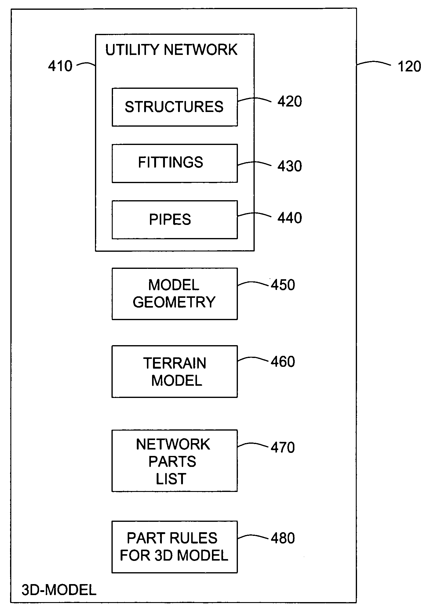
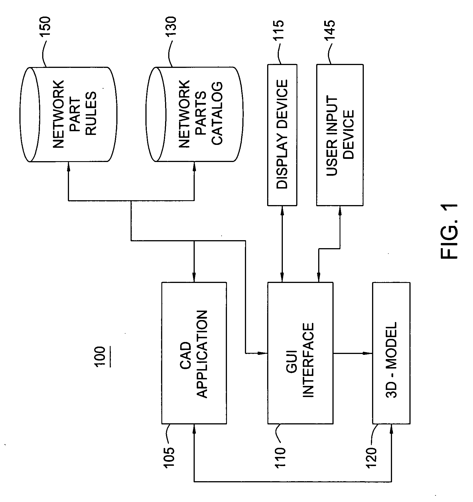
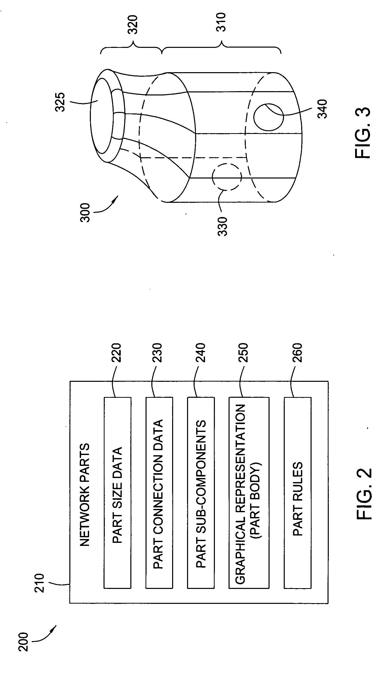
[0026] Embodiments of the invention provide a method, apparatus, and article of manufacture for creating a computer-generated three-dimensional model (3D model) of a utility network that is composed from many network part objects (or more simply, just “parts”). Each part inserted into a 3D model may correspond to a real-world component of a utility network. Similarly, the 3D model may include terrain features modeling a real world location. As parts are selected and placed within the 3D model, the CAD application may be configured to process a collection of rules associated with each individual part. The rules may be used to manage a custom set of criteria for a given design project. For example, the network part rules may be configured to modify the data or attributes associated with a part when it is placed in the 3D model. Alternatively, the rules may be applied to an existing 3D model to identify any network parts that fail to comply with a given rule. This allows a user to iden...


PUM


Abstract

One embodiment of the invention provides a method for modeling a variety of three-dimensional (3D) utility networks constructed from individual parts. In one embodiment, users may construct a utility network by selecting and assembling a network of inter-connected parts, where each part may be associated one or more design rules. When a part is placed within the model, the rules corresponding to the part may be applied. The network part rules may be configured to adjust the position, properties or attributes associated with a network part to comply with a rule. Alternatively, a user interface display may provide an indication of any network parts of a 3D model that violate a particular network part rule.

Description

CROSS REFERENCE TO RELATED APPLICATIONS [0001] This application is related to commonly assigned, co-pending U.S. Pat. application Ser. No., titled “Method for Dynamically Generating Multiple Views of Three-Dimensional Models for Utility Networks,” filed on Oct. 13, 2005 (Attorney Docket No. AUTO / 1008), incorporated fully herein by reference.BACKGROUND OF THE INVENTION [0002] 1. Field of the Invention [0003] The present invention generally relates to computer software. More specifically, the present invention relates to computer software applications configured to facilitate the interactive design of three-dimensional (3D) models of utility networks using a collection of customizable, dynamically applied design rules. [0004] 2. Description of the Related Art [0005] Currently, computer aided design (CAD) applications are available that allow a designer or engineer to compose a graphical representation of real-world three-dimensional (3D) structures. For example, computer aided design ...

Claims


Application Information

Patent Timeline
Patent Type & Authority Applications(United States)
IPC IPC(8): G06F9/44
CPCG06F17/50G06F2217/34G06F2217/06G06F2217/02G06F2111/20G06F2111/04G06F2113/14G06F30/00
Inventor CONNOR, EDWARD JAMESSTORMS, CRAIGAPPOLO, MICHAEL A. IIIBURNHAM, TIMMILLIGAN, STEVEROGERSON, MICHAEL C.SPALDING, KENNETH W. III
Owner AUTODESK INC
Why Eureka
Try Eureka