Feedback control of sub-atmospheric chemical vapor deposition processes

a sub-atmospheric chemical vapor and process control technology, applied in the direction of programme control, total factory control, instruments, etc., can solve the problems of sub-atmospheric chemical vapor deposition, deposited film to deviate significantly from target values, and radial and azimuthal thickness non-uniformity, both within and among wafers, to achieve the effect of improving the wafer-to-wafer and within-wafer uniformity of film

Inactive Publication Date: 2007-07-26
ADOBE SYST INC
View PDF109 Cites 12 Cited by
  • Summary
  • Abstract
  • Description
  • Claims
  • Application Information

AI Technical Summary

Benefits of technology

[0010] The present invention relates to a method, apparatus and medium for process control of sub-atmospheric chemical vapor deposition of a film onto a surface of a substrate, for example, a semiconductor wafer, in order to provide predetermined desirable film properties and improve wafer-to-wafer and within-wafer uniformity of film properties. The present invention uses a model (which can be implemented as a single model or multiple models) of the film deposition process to predict film deposition rate, film thickness uniformity and / or other film properties across the wafer surface. Deviations from the predicted outcome are used to update the model and set new deposition recipe parameters, which feed back into the process to enhance process results.
[0011] The use of multiple wafer regions in the deposition model that defines the deposited film (as contemplated by one or more embodiments of the present invention) provides greater control over the cross-film thickness. Furthermore, the methods, apparatus and mediums of the present invention (in one or more embodiments thereof) provide a model that distinguishes between depositions in different deposition chambers of the tool and between deposition parameters that are independently or commonly controlled for each chamber, thereby providing a better approximation of the tool behavior of each chamber. The methods, apparatus and mediums of the present invention (in one or more embodiments thereof also provide a model that defines the relationship between the deposition model variables and film properties other than film thickness, allowing control of the chemical, optical and / or material properties of the thin film. In addition, the methods, apparatus and mediums of the present invention (in one or more embodiments thereof) provide models that better approximate tool behavior by accounting for effects such as tool idle time, the effect of earlier-processed wafers on the current wafer, or the reliability of a value for a measured film quality. These and other aspects of the present invention allow for better estimation of tool behavior and the prediction of optimal deposition recipes for achieving a target output, thus overcoming deficiencies of the conventional technology.

Problems solved by technology

Thin film deposition is an inherently complex process, thereby making it hard to simultaneously control film characteristics, such as optical and electrical properties, stresses in the film, etc., while maintaining uniform film thickness.
Thin film deposition processes typically “drift” over time, causing the deposited film to deviate significantly from target values.
Specifically, sub-atmospheric chemical vapor deposition introduces both radial and azimuthal thickness non-uniformity, both within and among wafers.
While film thickness non-uniformity can be addressed in subsequent processing steps, the greater the deposition-induced non-uniformity, the more difficult it is to achieve within-wafer thickness uniformity in subsequent steps.
Implementation of process control in these operations has been limited due to unavailability of suitable integrated metrology tools, limited process understanding and non-automated operational practices.

Method used


Image

  • Feedback control of sub-atmospheric chemical vapor deposition processes
  • Feedback control of sub-atmospheric chemical vapor deposition processes
  • Feedback control of sub-atmospheric chemical vapor deposition processes

Examples


Embodiment Construction

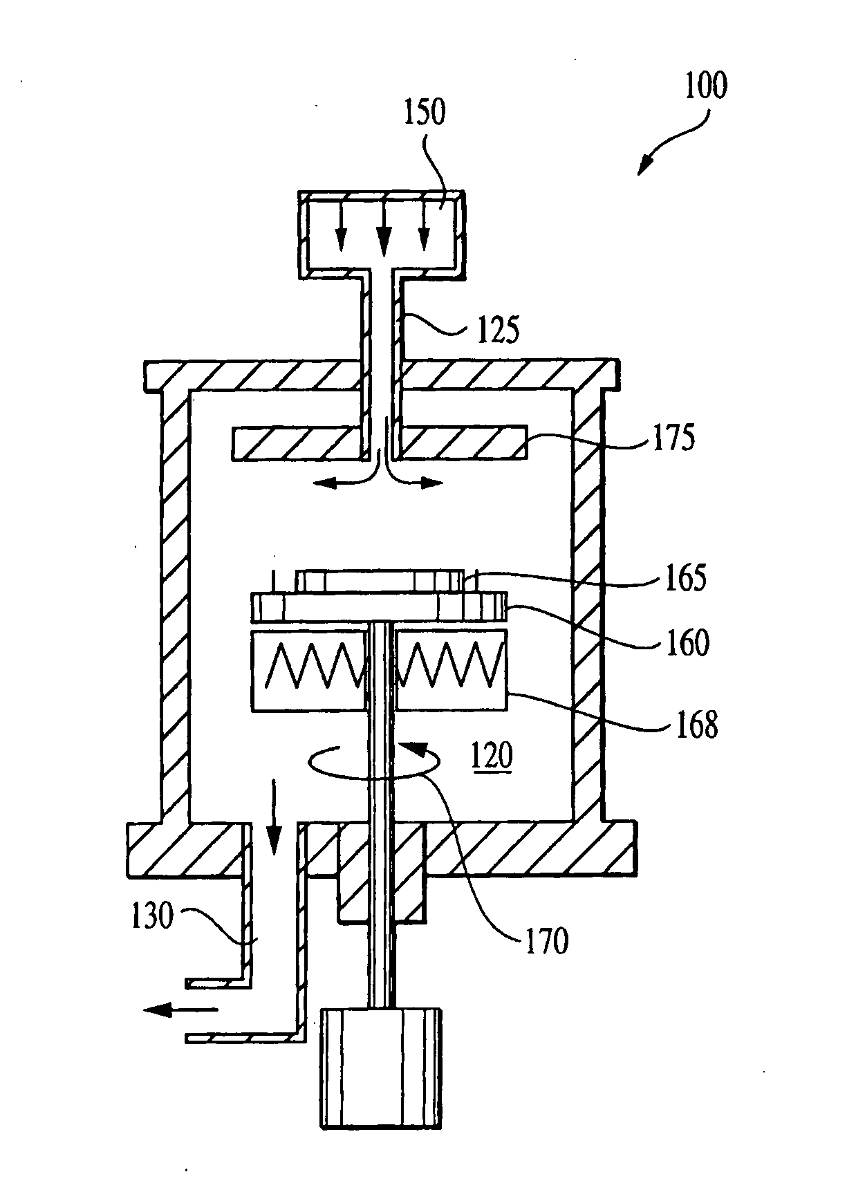
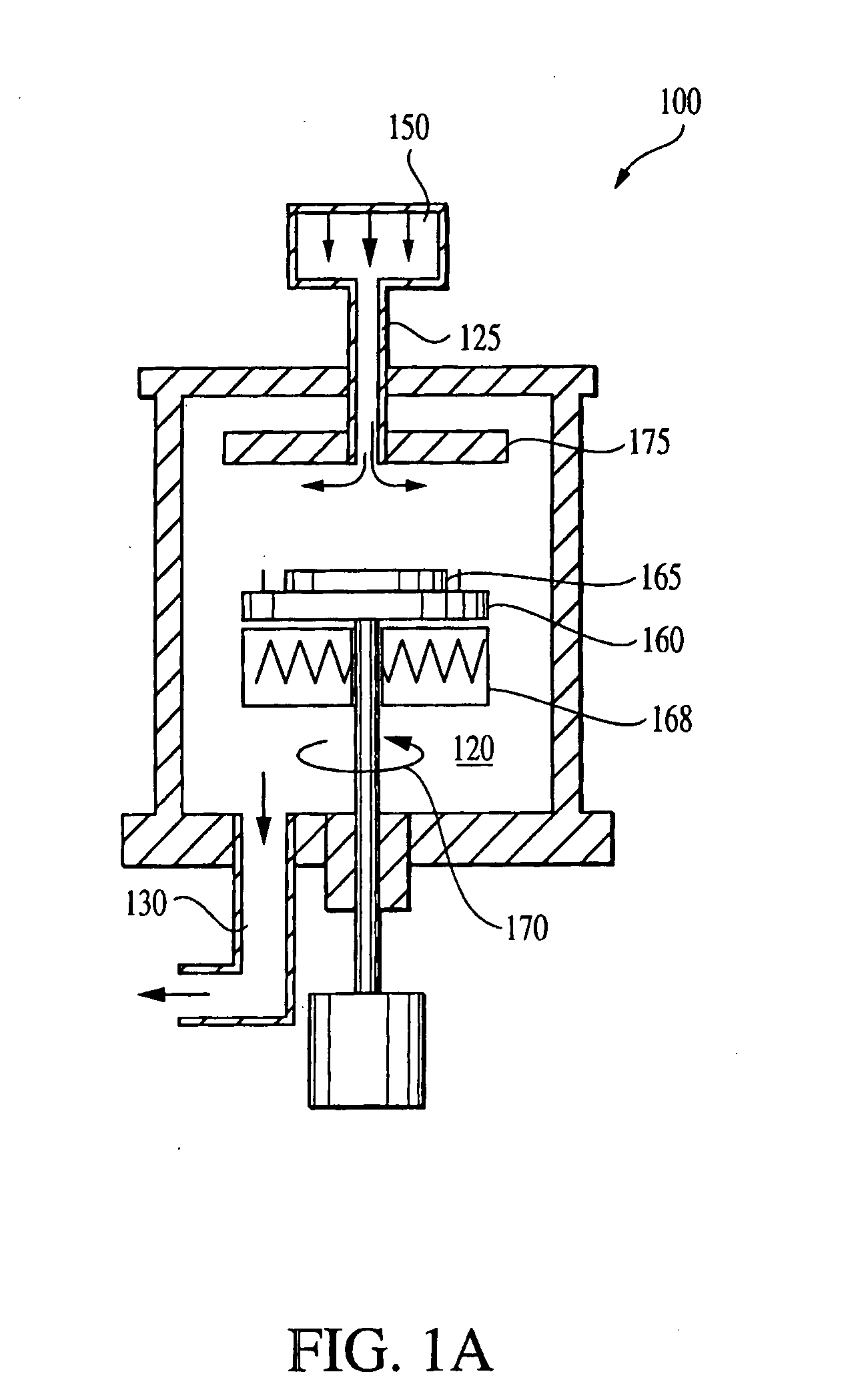
[0040] Sub-atmospheric chemical vapor deposition (SACVD) has been widely used in microelectronics fabrication to deposit films, such as a SiO2, at low temperatures. In the SACVD process, reactive gases are introduced into the reaction chamber at sub-atmospheric pressures. The reactive gases flow over a heated wafer (e.g., 300-700° C.) where the desired chemical reactions occur and the product is deposited. FIG. 1A is a schematic illustration of an exemplary SACVD system 100. The system 100 includes a chamber 120, a vacuum system 130, a wafer holder 160 for supporting wafer 165, a gas or fluid delivery system 150 for introduction of reactive gases and a heater 168 for heating the wafer holder 160. Reactive gases are introduced into a reaction chamber 120 through inlet 125 of the gas delivery system 150. In order to promote a uniform distribution, the reactive gases typically are introduced into the chamber at a source positioned opposite or a distance from the wafer 165. The heated w...


PUM

PropertyMeasurementUnit
diameteraaaaaaaaaa
thicknessaaaaaaaaaa
thicknessaaaaaaaaaa

Abstract

A method of film deposition in a sub-atmospheric chemical vapor deposition (CVD) process includes (a) providing a model for sub-atmospheric CVD deposition of a film that identifies one or more film properties of the film and at least one deposition model variable that correlates with the one or more film properties; (b) depositing a film onto a wafer using a first deposition recipe comprising at least one deposition recipe parameter that corresponds to the at least one deposition variable; (c) measuring a film property of at least one of said one or more film properties for the deposited film of step (b); (d) calculating an updated deposition model based upon the measured film property of step (c) and the model of step (a); and (e) calculating an updated deposition recipe based upon the updated model of step (d) to maintain a target film property. The method can be used to provide feedback to a plurality of deposition chambers or to control a film property other than film thickness.

Description

RELATED APPLICATIONS [0001] This application claims priority under 35 U.S.C. § 119(e) from provisional application Ser. No. 60 / 298,878 filed Jun. 19, 2001, which is incorporated by reference. [0002] This application claims priority under 35 U.S.C. § 119(e) from provisional application Ser. No. 60 / 349,576 filed Oct. 29, 2001, which is incorporated by reference. [0003] This application claims priority under 35 U.S.C. § 119(e) from provisional application Ser. No. 60 / 366,698, filed Mar. 21, 2002, which is incorporated by reference. [0004] This application is a divisional application of and claims priority from co-pending application Ser. No. 10 / 174,377, filed on Jun. 18, 2002 and entitled “Feedback Control of Plasma-Enhanced Chemical Vapor Deposition Process,” which is related to co-pending application filed on even date herewith and entitled “Feedback Control of Plasma-Enhanced Chemical Vapor Deposition Process,” which is incorporated by reference.FIELD OF THE INVENTION [0005] The pre...

Claims


Application Information

Patent Timeline
Patent Type & Authority Applications(United States)
IPC IPC(8): G06F19/00B05C11/00C23C16/00C23C16/52G05B19/00G05B19/19G05B19/418H01L21/00H01L21/66
CPCC23C16/52G05B19/00G05B19/19G05B19/41865H01L22/20G05B2219/32065G05B2219/45031H01L21/67253G05B2219/32053Y02P90/02
Inventor SCHWARM, ALEXANDER T.SHANMUGASUNDRAM, ARULKUMAR P.PAN, RONGHERNZNDEZ, MANUELMOHAMMED, AMNA
Owner ADOBE SYST INC
Why Eureka
Try Eureka