[0005] The present invention overcomes many of the shortcomings and limitations of the prior art devices and teaches the construction and operation of a rapid deployable weapon retention mechanism /
system for use with holsters which effectively incorporates a
high security retention mechanism with a rapid release mechanism for rapid retrieval and deployment of the weapon from the holster by an authorized user. The present retention mechanism /
system, when in its secured or locked position, effectively blocks the withdrawal of the weapon from the holster pocket and includes a quick release mechanism for allowing access to the weapon which can be activated by an authorized user in a single motion while the shooting hand is moving towards obtaining a firing grip on the holstered weapon. The present mechanism incorporates features that allow this economy of motion to be used to the
advantage by the authorized user. The present mechanism also allows for the user to re-set the retention system with a single motion once it has been released via the quick release mechanism.
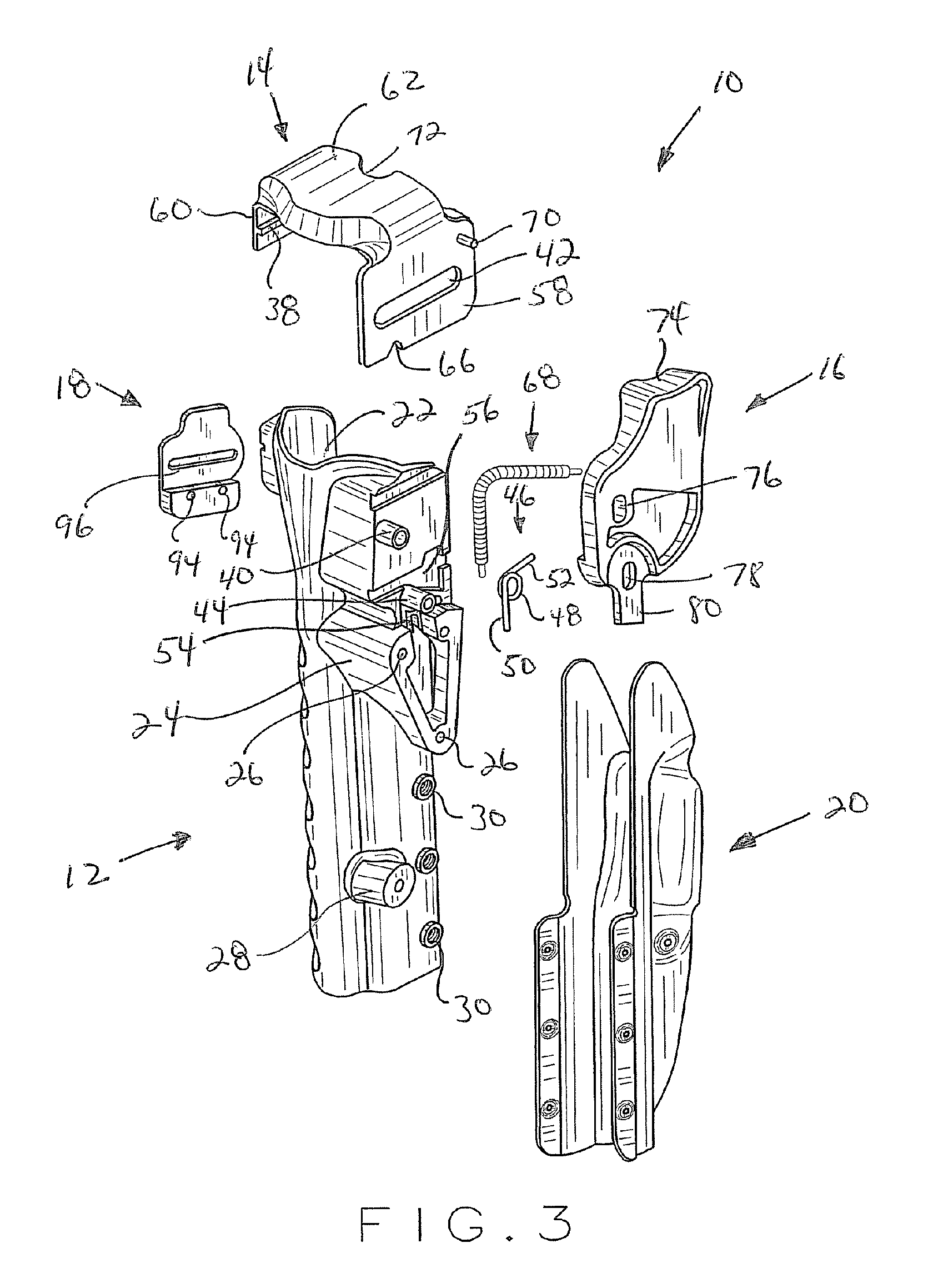
[0006] In one aspect of the present invention, the present weapon retention mechanism includes a frame member, a retention
canopy, and a release mechanism. The frame member is the primary support element for the holstering system. The frame member's internal geometry is typically matched to the particular handgun or weapon that is intended to be holstered therewith in so as to best enable a secure fit while providing a smooth snag-free draw. The external portions of the frame member facilitate attachment to various mounting platforms such as, for example, belt loops, leg panels, a
paddle, or a belt slide so that the weapon may be transported in a plurality of different ways that best meet the needs of the authorized user. The present frame member also provides attachment points for other components such as an interchangeable
cowling for holstering the weapon. The present frame member also serves as the main platform for the retention mechanism and it is molded to receive and support the specific components of the retention mechanism.
Modularity of carry and adaptability and precision matching of weapon to the holster are uniquely accomplished.
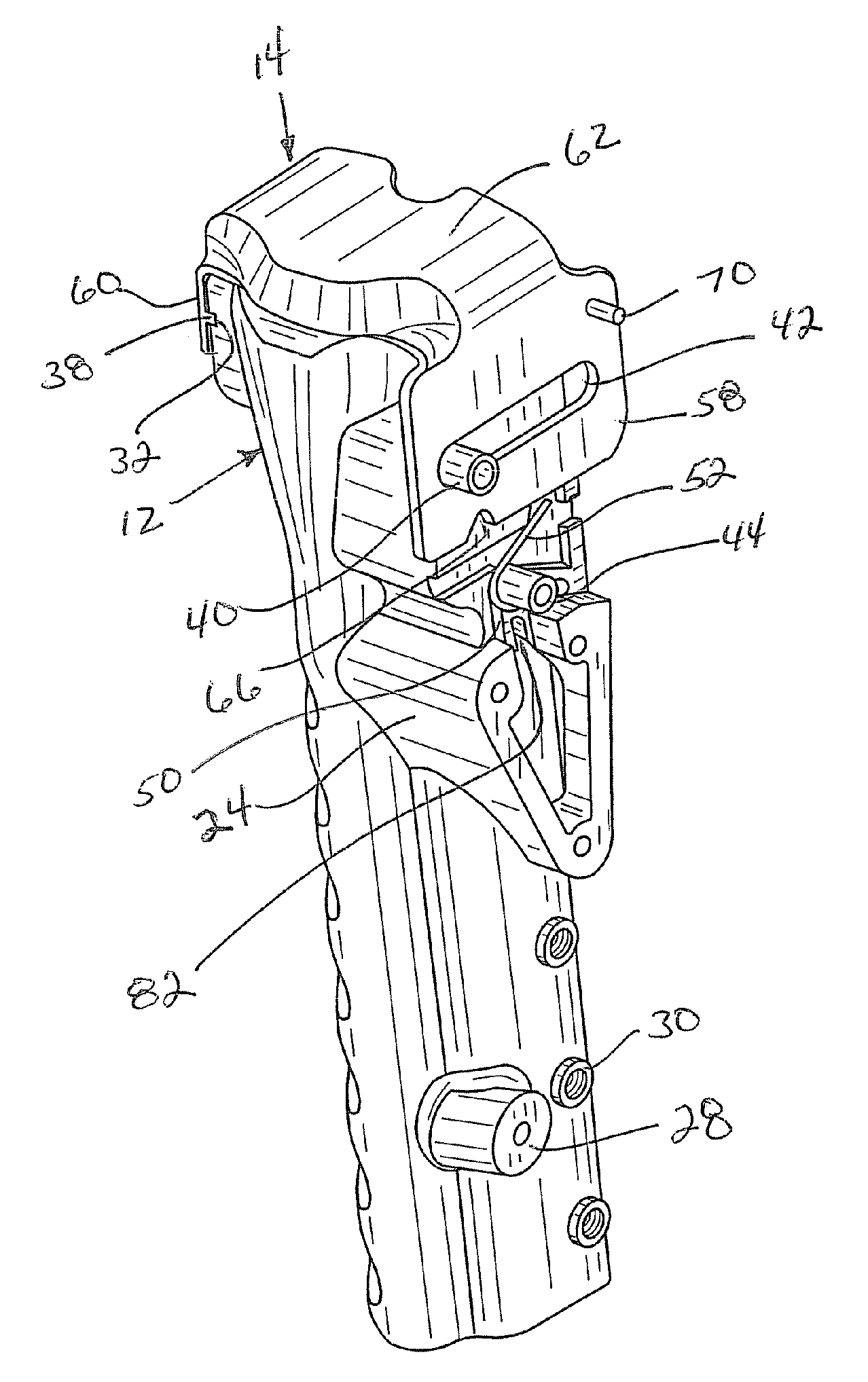
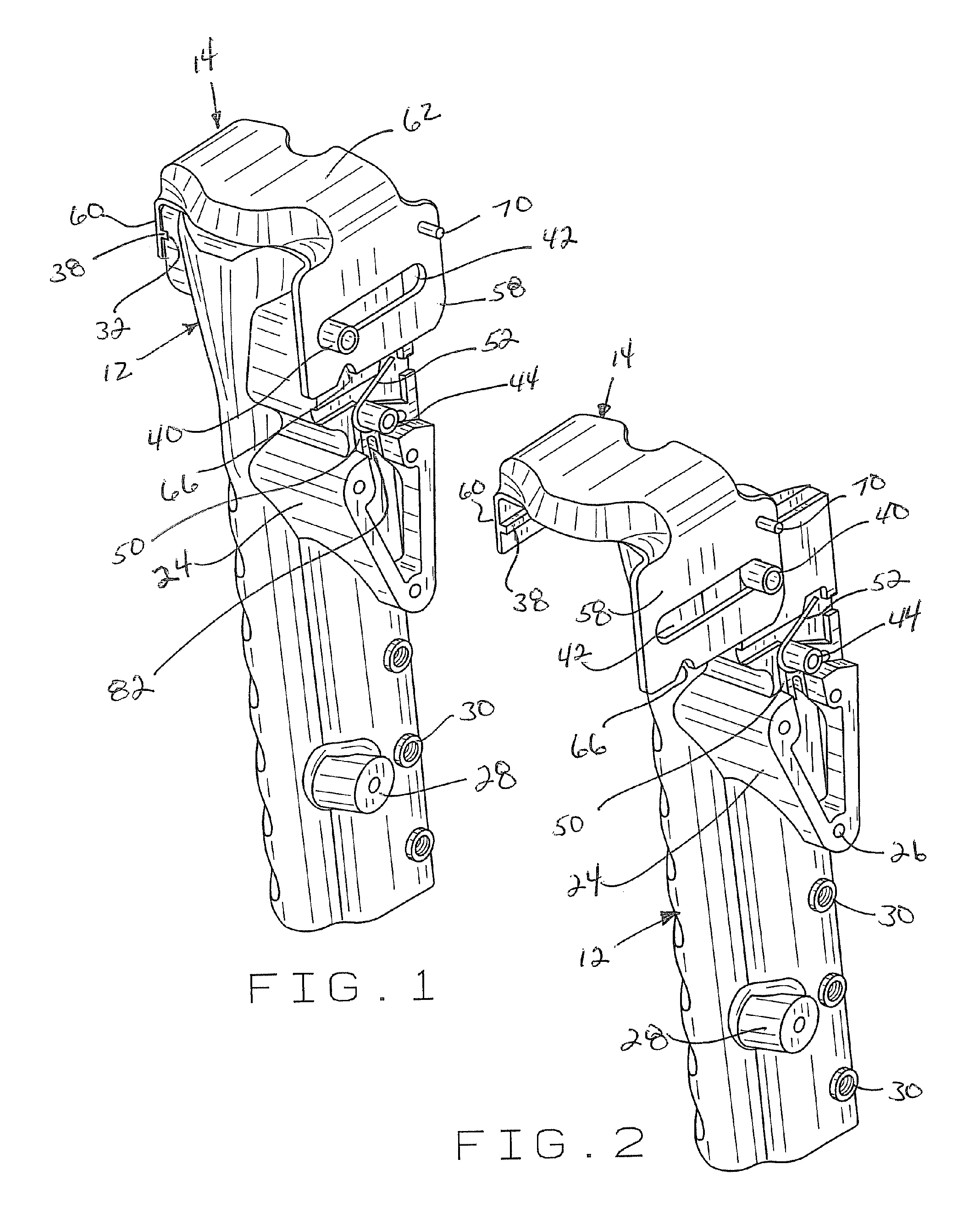
[0007] The retention
canopy is slidably attachable to the upper portion of the frame member and, when positioned in its locked position, covers the top portion of the holster and blocks the withdrawal of the weapon positioned therewith in. The retention
canopy is movably attachable to the frame member via a sliding
tongue and groove arrangement and via the use of a slot and boss arrangement. The retention canopy travels between a first locked and a second unlocked position in a substantially horizontal or linear direction and is biased to its unlocked position through the use of a drive spring. The boss associated with the frame member extends through the linear slot associated with one side of the retention canopy and serves as a stop member to limit the movement of the retention canopy as it travels back and forth between its locked and unlocked position. The boss / slot arrangement prevents the retention canopy from traveling past its desired stopping points associated with both its locked and unlocked position. When in its unlocked position, the weapon housed within the holster can be easily and rapidly withdrawn and deployed from the holster pocket for use.
[0009] When the retention canopy is moved into its locked position, the retention canopy bridges the side walls of the holster across the top portion thereof and actually wraps around the top, sides and front of the top portion of the holstered weapon thereby preventing the holstered weapon from being withdrawn from the holster pocket. The present retention canopy also provides additional protection to the weapon from the elements and prevents
dirt and dust from coming into contact with vital areas of the firearm. Upon activation of the release mechanism, the retention canopy, under the power of the canopy drive spring, is automatically and rapidly moved or snapped forward in a
linear motion from its locked position to its unlocked position, thereby clearing the path of the weapon for removal from the holster pocket. The release mechanism through engagement of the trigger pawl with the notch associated with the retention canopy prevents movement of the retention canopy out of its locked position until the
thumb button of the release mechanism is pressed downwardly by the user's
thumb to release the pawl and to allow the retention canopy to move forward in a
linear motion away from the holstered weapon. As a result, the present weapon retention system provides
high security when the retention canopy is in its locked position and likewise allows for rapid retrieval and deployment of the weapon by the authorized user when the retention canopy is moved to its unlocked position.
[0010] In another aspect of the present invention, the present weapon retention mechanism may likewise include a side cap member which reinforces and holds the retention canopy to the off-side of the frame member opposite the release mechanism so as to further ensure that the retention canopy remains attached to that side of the frame member. The side cap member also aids in limiting movement of the retention canopy and prevents the retention canopy from over travel in both directions.

