Tool holder with roller edge receiver
- Summary
- Abstract
- Description
- Claims
- Application Information
AI Technical Summary
Benefits of technology
Problems solved by technology
Method used
Image
Examples
embodiment 100
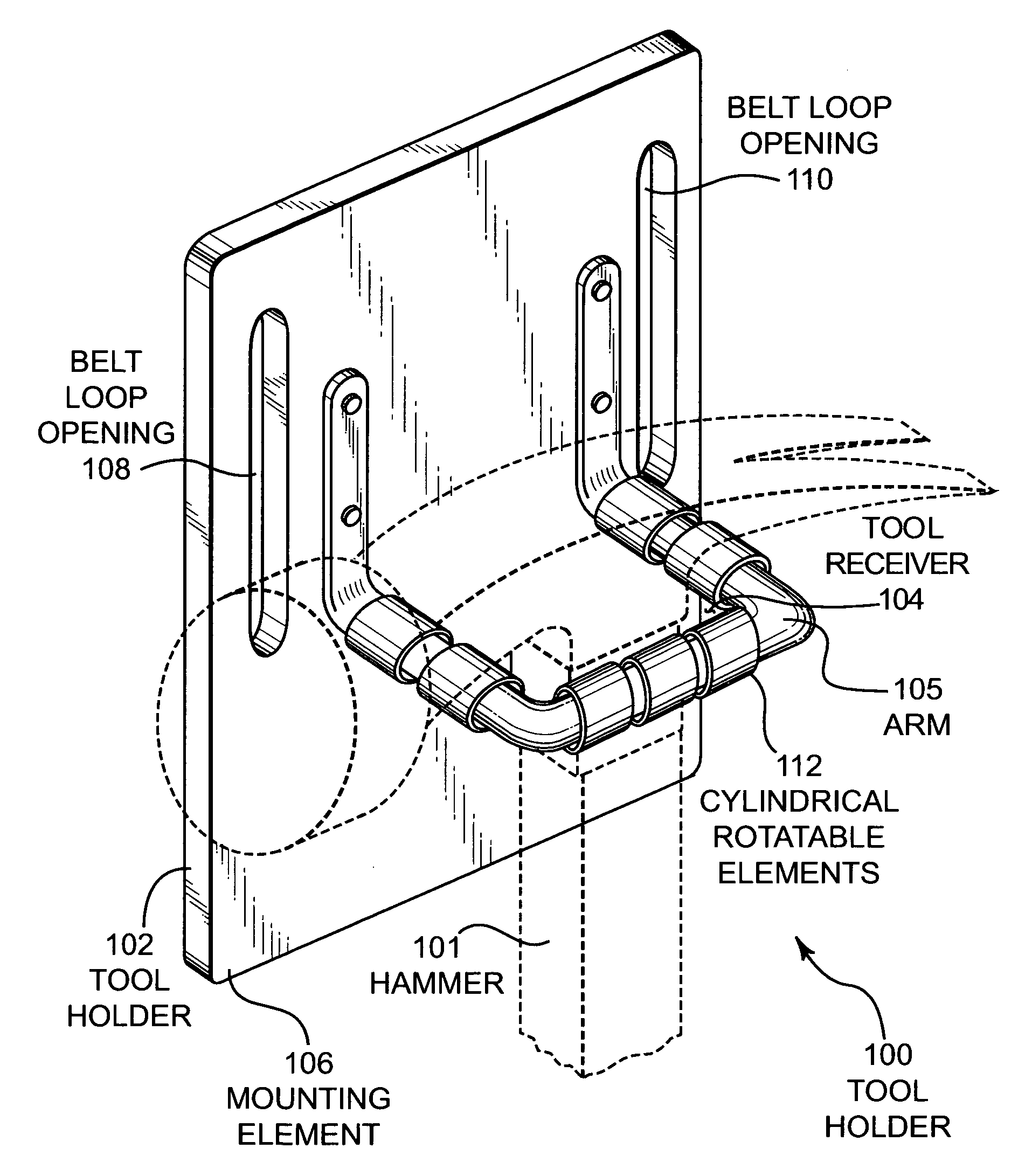
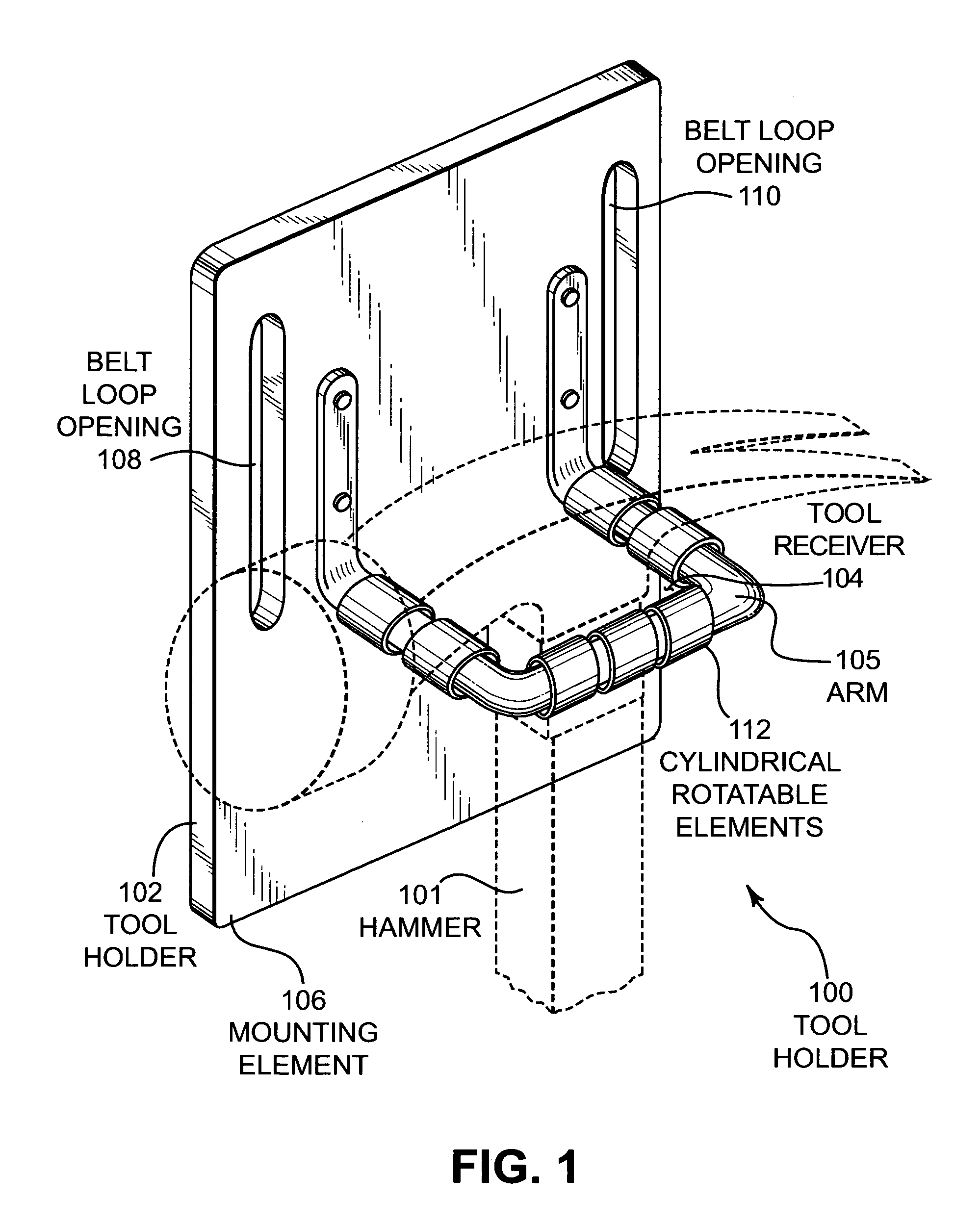
[0015]FIG. 1 illustrates an embodiment 100 showing a tool holder. A hammer 101 is shown being carried by the tool holder 102 that defines a tool receiver 104. The arm 105 is mounted to a mounting element 106. The mounting element 106 may be worn by a user by threading a belt through the belt loop openings 108 and 110. The arm 105 may have several rotatable elements 112 that allow the hammer 101 to be quickly removed from the tool receiver 104 with a minimum of friction.
[0016] The embodiment 100 illustrates one embodiment of a tool holder with rotatable elements disposed about three sides of the periphery of the tool receiver 104. The rotatable elements 112 may allow the hammer 101 to be removed without rubbing, dragging, or catching a portion of the hammer 101 on the tool holder 102. For example, if the hammer 101 has a sticky or tacky grip, the grip may drag on the edge of a conventional tool holder and make removal more difficult for the user. The rotatable elements 112 may rotate...
embodiment 200
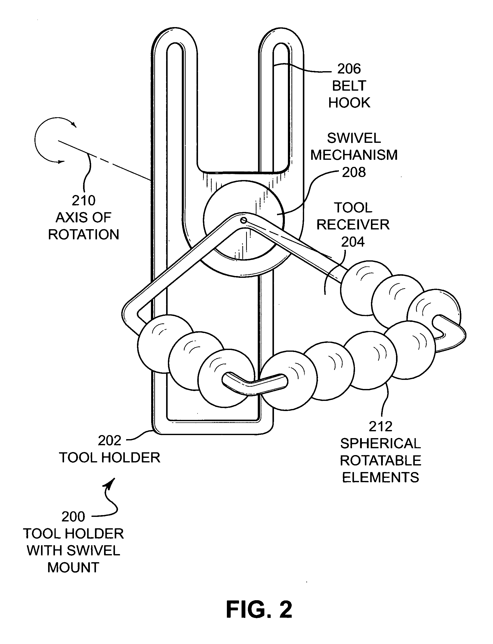
[0023]FIG. 2 illustrates an embodiment 200 of a tool holder with a swivel mounted tool receiver. The tool holder 202 comprises a tool receiver 204 that is attached to a belt hook 206 via a swivel mechanism 208 having an axis of rotation 210. Several spherical rotatable elements 212 are disposed about the periphery of the tool receiver 204.
[0024] The embodiment 200 may be manufactured from a formed metal belt hook 206 that may engage a wearer's belt by sliding vertically down and capturing the belt in the belt hook 206.
[0025] The swivel mechanism 208 may allow the tool receiver 204 to rotate such that a tool held in the tool receiver 204 will remain upright while a user may bend over or otherwise gesticulate during movement.
[0026] The rotatable elements 212 may have a hole about which it may rotate. The rotatable elements 212 may be inserted over the arm that forms the tool receiver 204.
[0027] Various components such as the belt hook 206 and tool receiver 208 may be manufactured f...
embodiment 300
[0028]FIG. 3 illustrates an embodiment 300 of a tool holder having two parallel arms that form a tool receiver. A hammer 301 is held in a tool holder 302 that comprises a mounting element 304 to which is attached arms 306 and 308. Mounted on each arm 306 and 308 are several rotatable elements 310.
[0029] The mounting element 304 may be constructed from a woven material, leather, or other suitable material that may be folded over to form a belt loop 305 for receiving a belt. The belt may be attached to a tool belt or any other means by which the tool holder 302 may be secured to the person of the wearer.
[0030] The arms 306 and 308 may form a tool receiver 312 that holds the hammer 301. The tool receiver 312 is an area defined on three sides by the horizontal portions of the arms 306 and 308 and the mounting element 304. The vertical portions at the ends of the arms 306 and 308 that are distal from the mounting element 304 may prevent the hammer 301 or other tool held in the tool rece...
PUM
 Abstract
Description
Claims
Application Information
 - R&D
- Intellectual Property
- Life Sciences
- Materials
- Tech Scout
- Unparalleled Data Quality
- Higher Quality Content
- 60% Fewer Hallucinations
Browse by: Latest US Patents, China's latest patents, Technical Efficacy Thesaurus, Application Domain, Technology Topic, Popular Technical Reports.
© 2025 PatSnap. All rights reserved.Legal|Privacy policy|Modern Slavery Act Transparency Statement|Sitemap|About US| Contact US: help@patsnap.com


