Drives pertaining to a reel changer

a technology of drives and reel changers, applied in the field of drives of reel changers, can solve problems such as the inability to tense the cones, and achieve the effects of preventing friction, high functionality, and reducing the cost of components

a technology of drives and reel changers, applied in the field of drives of reel changers, can solve problems such as the inability to tense the cones, and achieve the effects of preventing friction, high functionality, and reducing the cost of components

US20070170299A1Inactive Publication Date: 2007-07-26KOENIG & BAUER AG

Image

  • Drives pertaining to a reel changer
  • Drives pertaining to a reel changer
  • Drives pertaining to a reel changer

Examples


Embodiment Construction

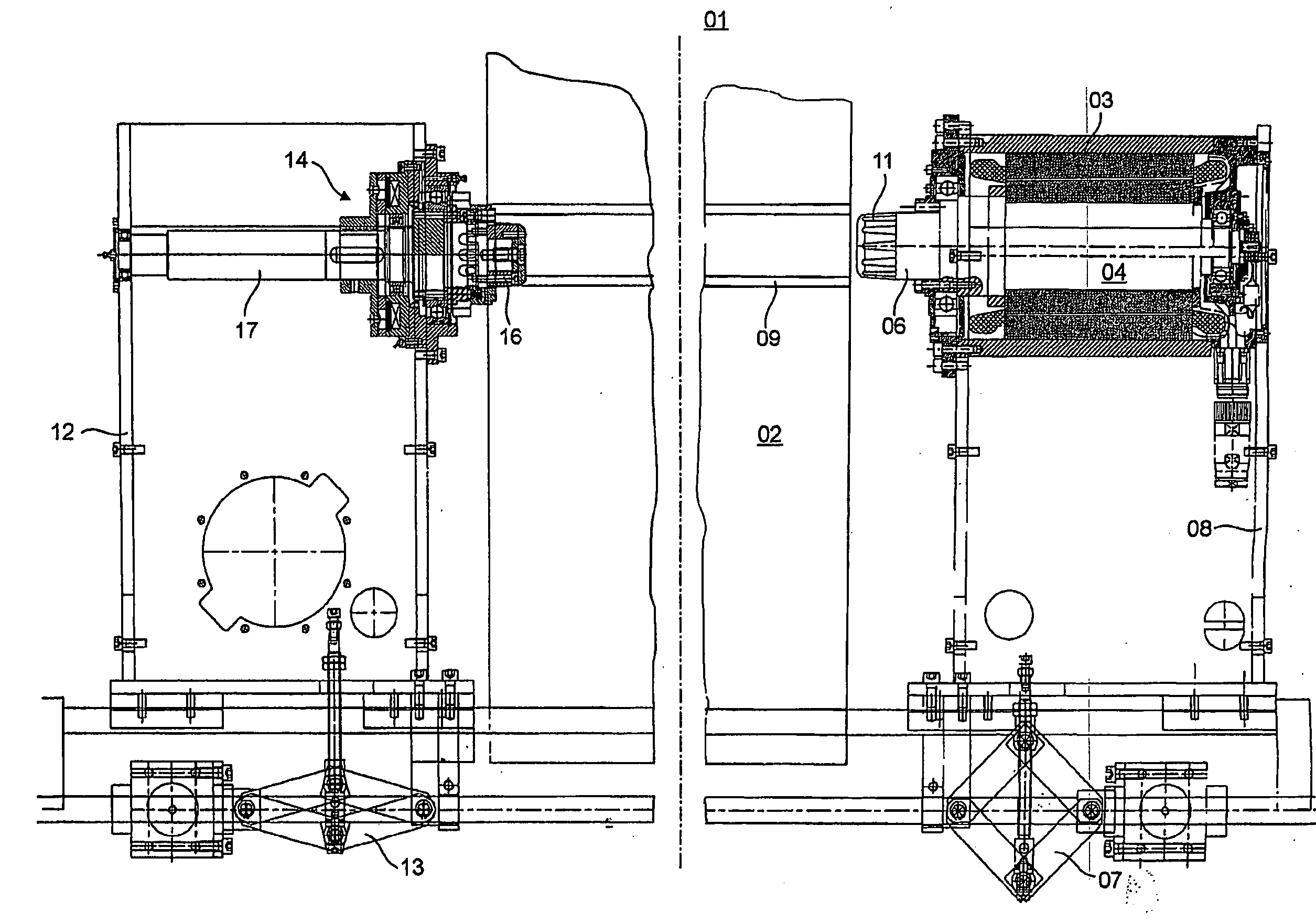
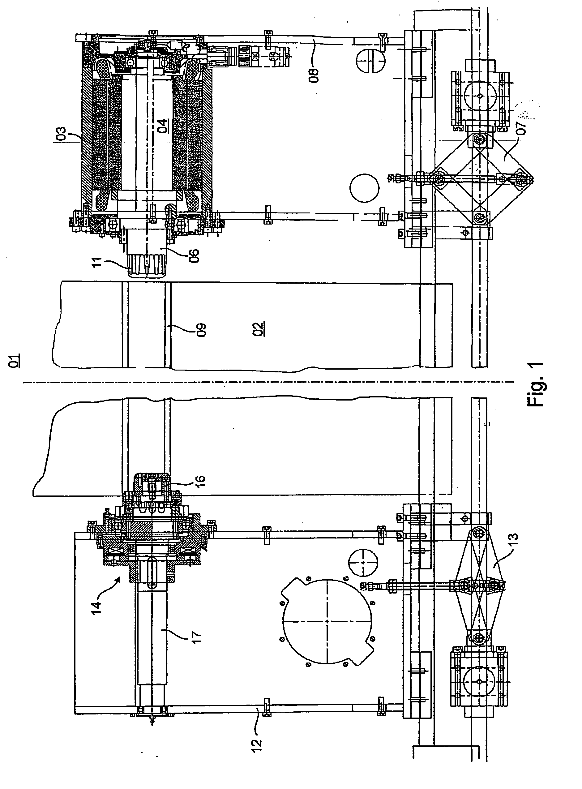
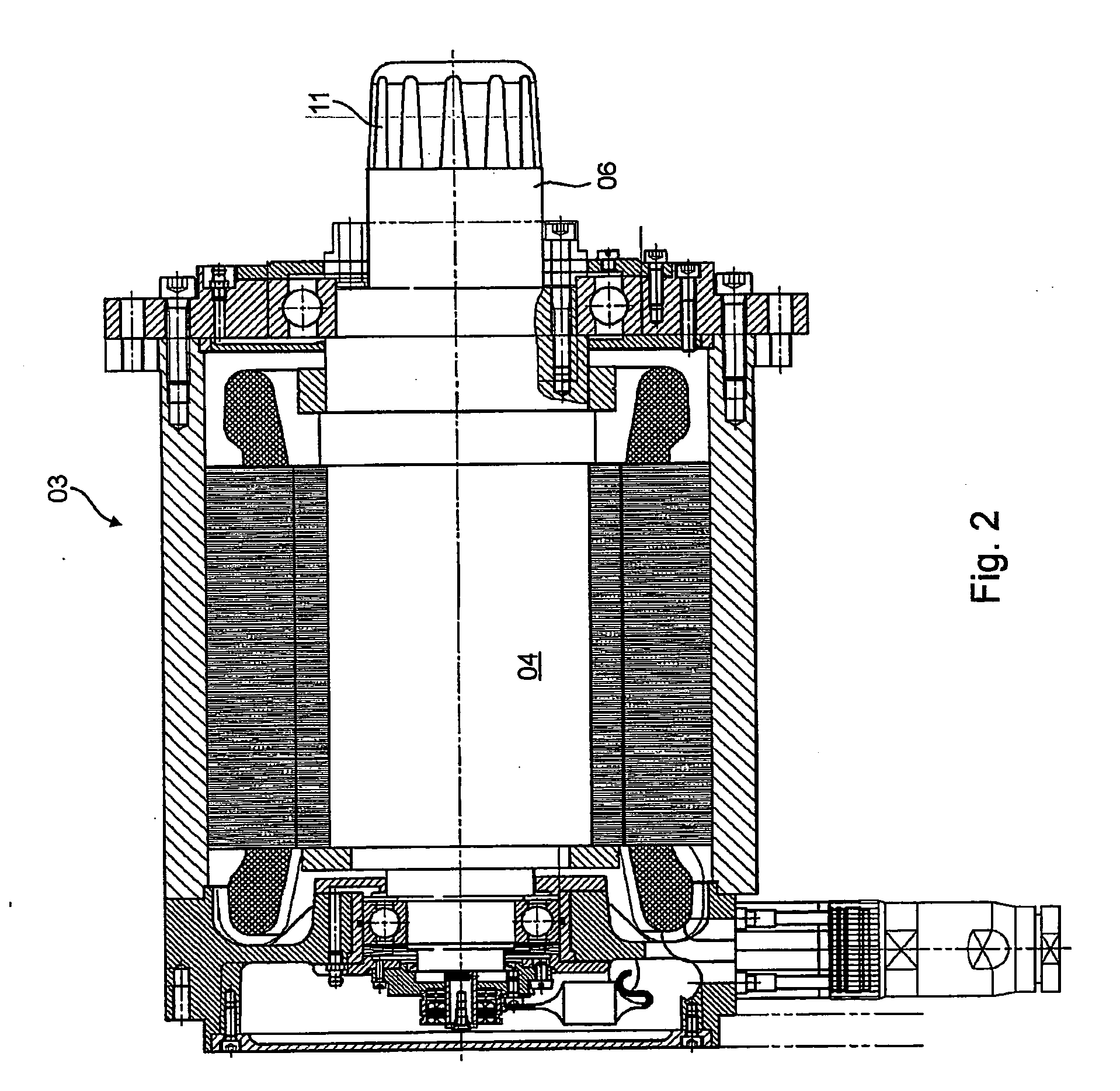
[0043] Referring initially to FIG. 1, there is shown a partial cross-sectional view of a reel changer 01, and in particular a reel changer for a rotary, web-fed printing press, for use in supporting a supply reel 02 having a width, of for example, from 300 mm to 1000 mm, and upon which a material web, such as, in particular, a web of printable material, has been wound. For the purpose of driving the supply reel 02, a motor 03, and in particular a synchronous motor 03, has been provided on one side of the supply reel 02. The synchronous motor 03 has a drive shaft 04 that protrudes past the housing of the synchronous motor 03 on a side of the motor which is facing the supply reel 02. This protruding side of the drive shaft 04 serves as a receiving unit 06, upon which the supply reel 02 may be rotationally supported.

[0044] An axial adjustor 07, which, as may also be seen in FIG. 1, is embodied in the manner of a scissor lever mechanism, supports a bracket 08 that is mounted in a shift...


PUM

PropertyMeasurementUnit
widthaaaaaaaaaa
displacementaaaaaaaaaa
rotationaaaaaaaaaa

Abstract

A drive for a reel changer includes at least one electric motor. This drive is used to rotatably drive a web supply roll that is held in the reel changer. A web of material is wound on the supply roll. The electric motor is embodied as a synchronous motor.

Description

CROSS-REFERENCE TO RELATED APPLICATIONS [0001] This application is the U.S. national phase, under 35 USC 371, of PCT / EP2005 / 050308, filed Jan. 25, 2005, published as WO 2005 / 073114 A2 on Aug. 11, 2005 and claiming priority to DE 10 2004 004 759.6, filed Jan. 30, 2004 and to DE 10 2004 030 490.4, filed Jun. 24, 2004, the disclosures of which are expressly incorporated herein by reference.FIELD OF THE INVENTION [0002] The present invention is directed to drives of a reel changer. The drive includes at least one electric motor which drives a material reel, held in the reel changer, in a rotational manner. BACKGROUND OF THE INVENTION [0003] EP 1 155 987 A2 discloses a reel changer for a printing press. To drive the supply reels in this reel changer, three-phase asynchronous motors, general rotary current motors or alternating current motors, universal motors, or direct current motors are provided. In accordance with one embodiment, the supply reels may be driven only on one side of the ...

Claims


Application Information

Patent Timeline
26 Jul 2007
Publication
US20070170299A1
IPC
B65H19/22; B65H16/10; B65H18/10; B65H19/12; B65H23/185; B65H54/54; B65H75/24
CPC
B65H16/103; B65H18/10; B65H19/12; B65H19/126; B65H19/2207; B65H23/185; B65H2408/24153; B65H2301/418523
Inventors
RITTER, WALTER