Cable protection and guide device

a technology of guide device and cable, which is applied in the direction of machine supports, instruments, printing, etc., can solve the problems of large amount of assembly, large number of parts, and long time and effort required for mutual connection and disconnection of side plates, and achieve excellent fatigue resistance to repeated flexion, excellent stability and form, and high rigidity.

Active Publication Date: 2007-07-26
TSUBAKIMOTO CHAIN CO
View PDF15 Cites 19 Cited by
  • Summary
  • Abstract
  • Description
  • Claims
  • Application Information

AI Technical Summary

Benefits of technology

[0013]First, according to the cable or the like protection and guide device of the invention, since a number of pairs of right and left spaced side plates are connected to each other in a longitudinal direction and connecting arms are bridged over flexional inner circumferential sides and flexional outer circumferential sides of the side plates in predetermined intervals, a cable or the like can be accommodated in a cable accommodating space surrounded by the side plates and the connecting arms along the longitudinal direction.
[0014]Each of the side plates are formed of a highly-rigid resin front side plate portion connected to a preceding side plate. Each of the rear side plate portions are formed of a highly-rigid resin rear side plate portion connected to a subsequent side plate. Each of the coupling portions of the side pates are formed of flexible fatigue resistant resins. Each of the coupling portions are interposed between the front side plate portion and the rear side plate portion in an integrated manner by a two-color molding process. As such, the front side plate portion and the rear side plate portion are strongly integrated through the two-color molded coupling portion. Thus, given the features of the side plates and their construction, inadvertent disconnection, which is liable to occur in the coupling portion of a side plate due to the repetition of flexional operation, can be prohibited, reduced or resolved. Further, since a coupling portion made of a fatigue resistant resin is flexibly provided for repeated flexion, an excellent fatigue resistance to repeated flexion is exhibited. And since the front side plate portion and the rear side plate portion which are made of a highly-rigid resin concentrically transfers a flexional strain, which is liable to occur during a flexional operation, to the coupling portion to be absorbed therein, the cable or the like protection and guide device of the invention exhibits excellent stability and form.
[0015]Further, according to the cable or the like protection and guide device of the invention, since the highly-rigid resin is a polyamide 6-GF (glass fiber) compounding agent and the fatigue resistant resin is a polyamide 66-rubber compounding agent, the GF compounded in polyamide 6 as a highly-rigid resin adds extremely high rigidity to the resin whereby excellent stability and form can be exhibited. Further, since a rubber component adds strong flexibility to the impact resistance by being compounded with polyamide 66 as a fatigue resistance resin, an excellent fatigue resistance to repeated flexion is attained.
[0016]These and other objects of the invention will be better understood when reference is made to the

Problems solved by technology

As such a large number of parts are required with a significant amount of assembly required.
Further, in such an energy guide chain as in the Patent Reference 1, since a side plate and a coupling element are separately formed, there was a troublesome problem in maintenance that mutual connection and disconnection of the side plates took much time and effort.
Further, in the energy guide chain as in the Patent Reference 1, since the side plates are connected to each other by fitting coupling elements separate from the side plate between the side plates, there was a problem that displacements were gradually generated between a side plate and a connecting member by repetition of flexional operations between links and the chain would break and disconnect at the coupling portion.
Further there was a problem that in a case where no displacement between a side plate and a coupling element in such a coupling portion occurred, an excessive stress concentration was generated at the coupling portion during a flexional operation so that the coupling portion was prematurely broken.
As such, there was a possibility that the flexional portion composed of connecting rods would break so shortening the service life of the guide.
That is, in the protection and guide device of Patent Reference 2, there was a problem that the connecting rod would be broken by the load applied during restriction of flexion shortening service life.
Further, in the protection and guide device of Patent Reference 2, since the side plates are connected to each other by fitting a connecting rod between the side plates into a connecting groove, there was a problem that displacements gradually generated between the connecting rod between the side plates and the connecting groove by repetition of flexional operations between link bodies and the guide device caused breakage at a coupling portion.
Further there was a problem that even in the case where no displacement between the connecting rod and the connecting groove in such a coupling portion occurred, an excessive stress concentration was generated at the proximal portion of the connecting rod during a flexional operation so that a connecting rod protruding from the side plate would be prematurely broken.

Method used


Image

  • Cable protection and guide device
  • Cable protection and guide device
  • Cable protection and guide device

Examples


example

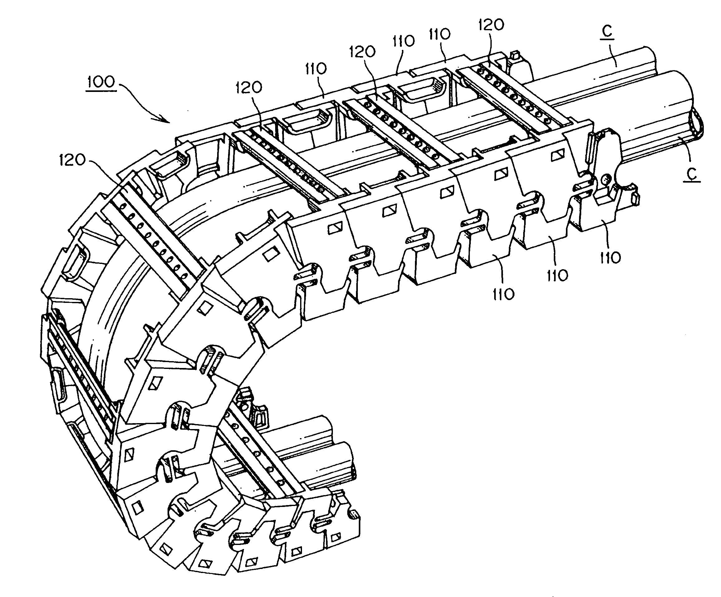
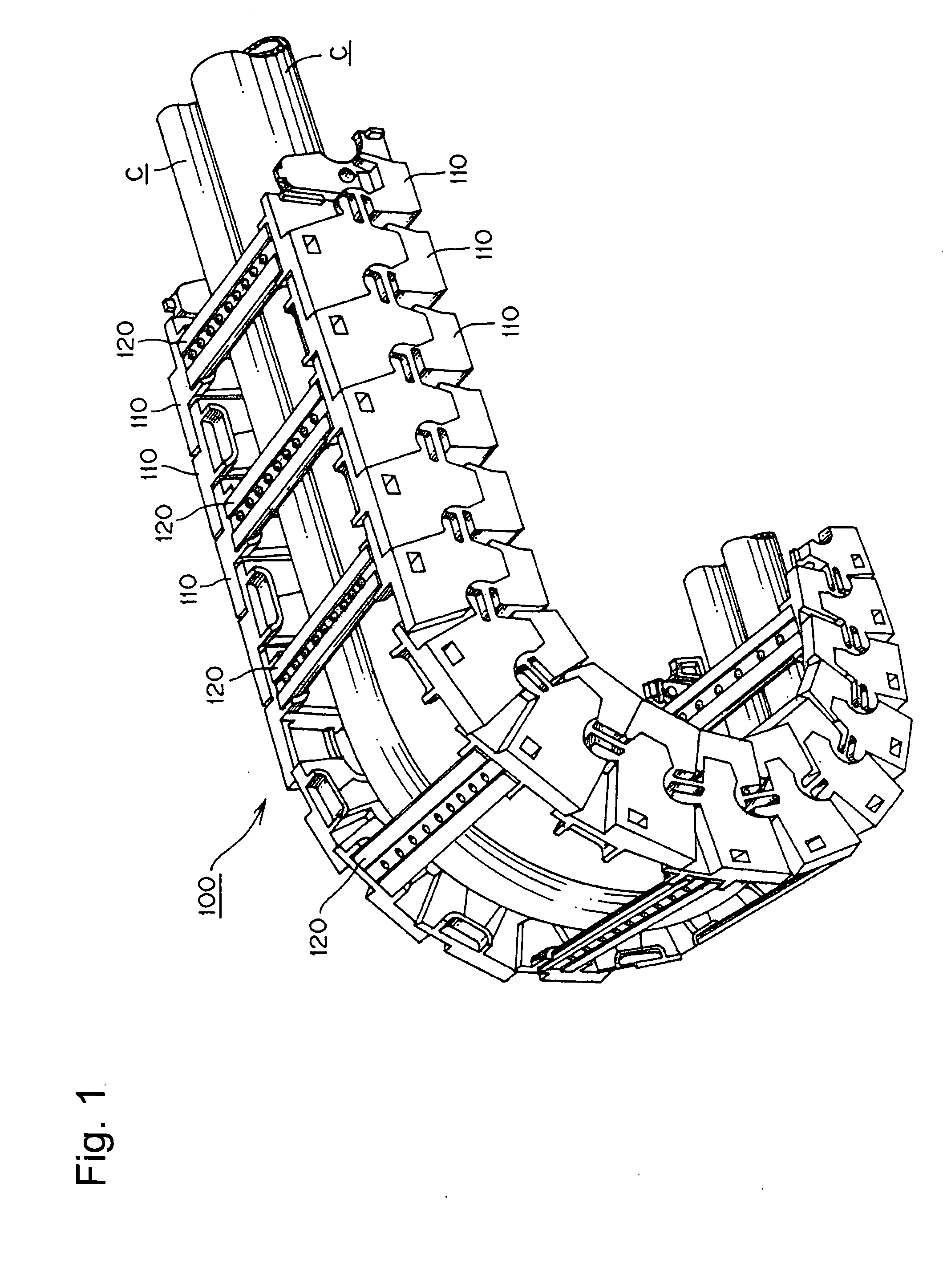
[0034]A cable or the like protection and guide device 100, which is an example of the present invention, will be described with reference to FIGS. 1 and 9.

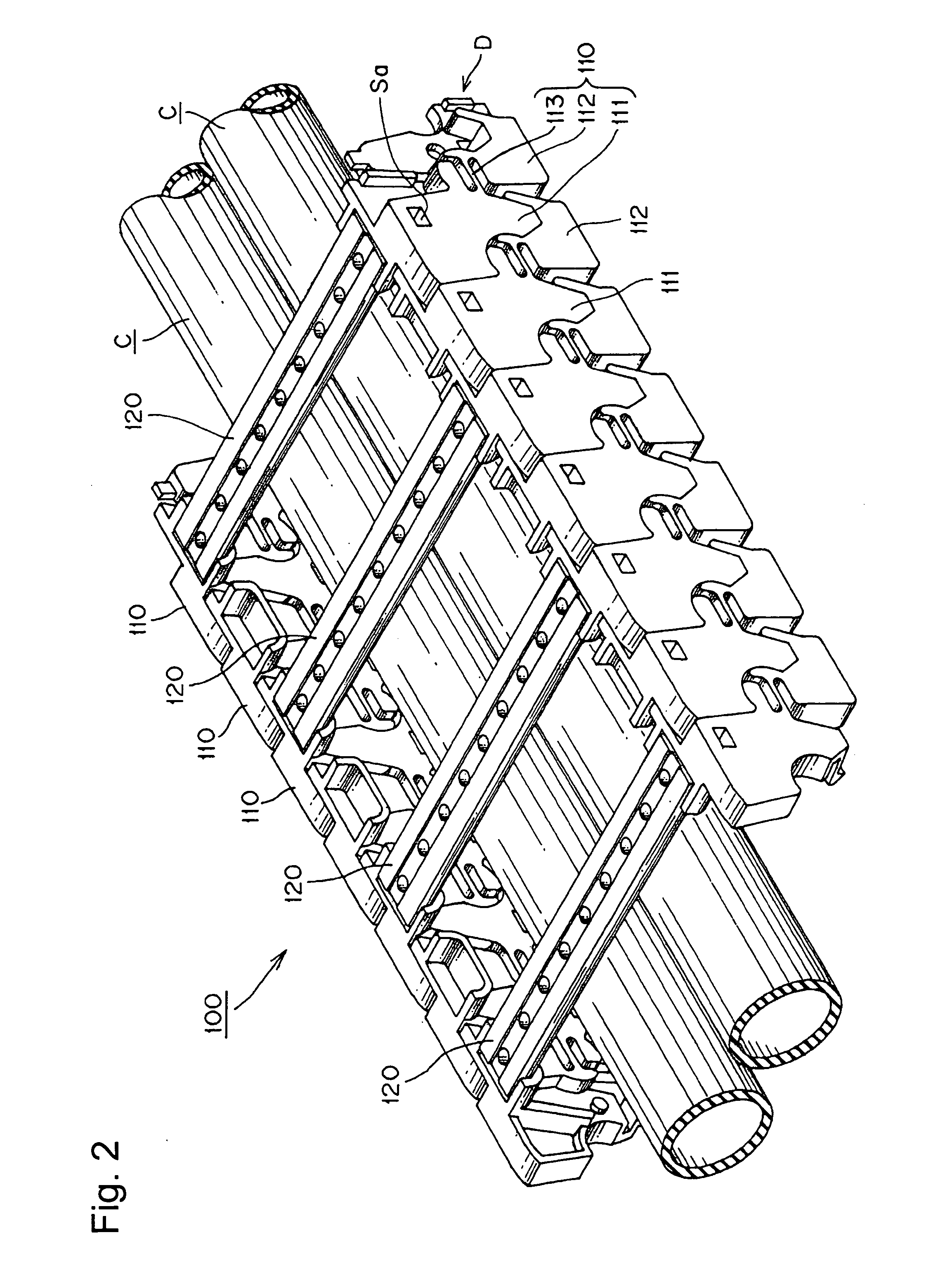
[0035]Here, FIG. 1 is an entire view of a cable or the like protection and guide device100, which is an example of the present invention. FIG. 2 is a perspective view of a linear connection state in the cable or the like protection and guide device 100 in FIG. 1. FIG. 3 is a perspective view of a flexional connection state in the cable or the like protection and guide device 100 in FIG. 1. FIG. 4 is a side view of a side plate used in the cable or the like protection and guide device 100 in FIG. 1. FIG. 5 is an enlarged cross-sectional view of an area in the vicinity of a coupling portion shown by V in FIG. 4. FIGS. 6 to 9 are perspective views of the side plate used in the cable or the like protection and guide device 100. Particularly, FIG. 6 is a perspective view of a side plate shown by an arrow D in FIG. 2. FIG. 7 is a perspe...


PUM


Abstract

A cable or the like protection and guide device is disclosed which prevents inadvertent disconnection due to repeated flexure. Excellent fatigue resistance is exhibited. A cable or the like protection and guide device in which pairs of side plates are respectively formed of a highly-rigid resin front side plate portion connected to a preceding side plate and a highly-rigid resin rear side plate portion is connected to a subsequent side plate. A flexible fatigue resistant resin coupling portion is interposed between the front side plate portion and the rear side plate portion in an integrated manner by using a using two-color molding.

Description

[0001]This application claims priority of Japanese patent Application No. 2006-012740 filed Jan. 20, 2006.TECHNICAL FIELD[0002]The present invention relates to a cable protection and guide device. More specifically it relates to a cable protection and guide device suitable for accommodating a cable (cables) or a hose (hoses) which supplies a movable member of an industrial machine with electric power or compressed air. The machine safely and reliably guides and protects a cable (cables) during movement of the movable portion.BACKGROUND TECHNOLOGY[0003]A conventional cable protection and guide device known as an energy guide chain includes side plates connected to each other with coupling elements separate from the side plate. See, for example, Patent Reference 1 which is published Japanese translation of PCT application no. 2004-527706.[0004]Alternatively, another conventional cable protection and guide device is known which includes side plates connected to each other by fitting co...

Claims


Application Information

Patent Timeline
Patent Type & Authority Applications(United States)
IPC IPC(8): B65H57/04
CPCH02G11/006F16G13/16
Inventor UTAKI, AKIHIKOIKEDA, MASAAKIKOMIYA, SHOICHIRO
Owner TSUBAKIMOTO CHAIN CO
Why Eureka
Try Eureka