Multimode optical fiber for high rate LAN, method for manufacturing the same , and test bed thereof

a multi-mode optical fiber and high-rate lan technology, applied in the field of multi-mode optical fiber, can solve the problems of affecting the performance of the system, and being difficult to cope with the bandwidth demand of subscribers, etc., and achieve the effect of eliminating the drawbacks of the core region

Inactive Publication Date: 2007-07-26
LG CABLE LTD (KR)
View PDF9 Cites 33 Cited by
  • Summary
  • Abstract
  • Description
  • Claims
  • Application Information

AI Technical Summary

Benefits of technology

[0024] The present invention is designed in consideration of such problems, and therefore it is an object of the present invention to provide a method for manufacturing a multimode optical fiber which may eliminate drawbacks of a core region, caused by evaporation of an additive for controlling a refractive index during a collapse process in MCVD (Modified Chemical Vapor Deposition).
[0027] In order to accomplish the above object, the present invention provides a method for manufacturing a multimode optical using MCVD, which includes a deposition process for forming a clad layer and a core layer, to which an additive for controlling a refractive index is doped, on an inner wall of a quartz tube by injecting a deposition gas into the quartz tube and applying heat to outside of the quartz tube; and a collapse process, which is repeatedly conducted N times, for filling up a gap in the quartz tube by applying heat of a temperature over a deposition temperature to the quartz tube after the core layer is completely deposited, wherein, together with an N−1th collapse process, an etching process of injecting a reaction gas for etching into the quartz tube is conducted in order to eliminate a portion of which refractive index is transformed due to evaporation of the additive.

Problems solved by technology

However, in spite of such expectation, the existing gigabit-level LAN system is not easy to cope with subscriber's demand for bandwidth, which is explosively increased, due to its structural disadvantage that it generally uses LEDs as a light source.
However, though advantageously supporting a high data rate communication over a gigabit level, the laser diode causes several problems when it is used together with a multimode optical fiber, differently from LED.
Representatively, since a laser diode is configured to irradiate a light only to a partial area of a core center of an optical fiber when the gigabit-level system is used, fine defects and irregularity in the core may sensitively transform an output signal, thereby exerting serious effects on performance deterioration of the system.
Such index dip and index peak, and resultant axial irregularity of refractive index, significantly reduce a bandwidth of a multimode optical fiber, thereby deteriorating optical characteristics thereof.
However, this technique conducts several times of the etching process separatively just before the final collapse process, so a time gap exists between N−1th and Nth collapse steps and thus GeO2 is volatilized during the etching process.
In addition, since there is a limit in decreasing an inner diameter of the tube just before the final collapse process due to the etching process, a volatilizing area of GeO2 is still large, so it is substantially not easy to effectively eliminate the index dip.
Though such various techniques are proposed, there is realistically not obtained a multimode optical fiber whose drawbacks are sufficiently eliminated to be suitable for a gigabit level high data rate transmission system, so there is still a need for a new method capable of more effectively eliminating drawbacks of the core center such as an index dip and an index peak.
However, the kinds of light sources to which RMLB may be applied are restricted, so, if a light source or a light-exciting condition is changed in the actual use, a critical error may arise since RMLB does not satisfy an actually demanded bandwidth.

Method used


Image

  • Multimode optical fiber for high rate LAN, method for manufacturing the same , and test bed thereof
  • Multimode optical fiber for high rate LAN, method for manufacturing the same , and test bed thereof
  • Multimode optical fiber for high rate LAN, method for manufacturing the same , and test bed thereof

Examples


Embodiment Construction

[0052] Hereinafter, the present invention will be described in more detail referring to the drawings. Prior to the description, it should be understood that the terms used in the specification and appended claims should not be construed as limited to general and dictionary meanings, but interpreted based on the meanings and concepts corresponding to technical aspects of the present invention on the basis of the principle that the inventor is allowed to define terms appropriately for the best explanation. Therefore, the description proposed herein is just a preferable example for the purpose of illustrations only, not intended to limit the scope of the invention, so it should be understood that other equivalents and modifications could be made thereto without departing from the spirit and scope of the invention.

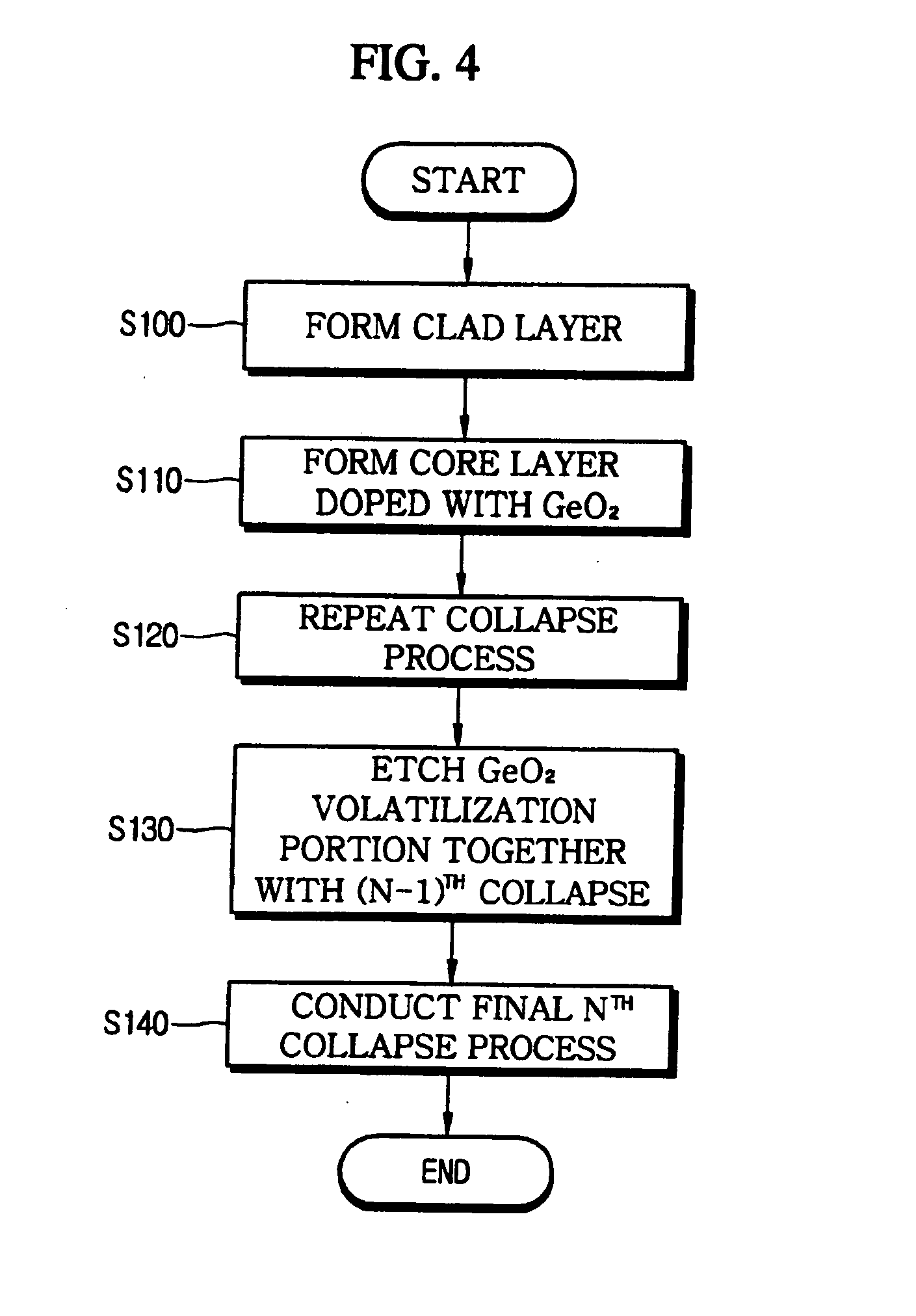
[0053]FIG. 4 is a flowchart for illustrating a method for manufacturing a multimode optical fiber according to a preferred embodiment of the present invention.

[0054] Referri...


PUM

PropertyMeasurementUnit
core diameteraaaaaaaaaa

Abstract

Disclosed is a method for manufacturing a multimode optical fiber for high data rate LAN using MCVD, which includes a deposition process for forming a clad layer and a core layer, doped with an additive for controlling a refractive index, on an inner wall of a quartz tube by injecting a deposition gas into the quartz tube and applying heat to outside of the quartz tube; and a collapse process, which is repeatedly conducted N times, for filling up a gap in the quartz tube by applying heat of a temperature over a deposition temperature to the quartz tube after the core layer is completely deposited. In the method, together with an N−1th collapse process, an etching process of injecting a reaction gas for etching into the quartz tube is conducted in order to eliminate a portion of which refractive index is transformed due to evaporation of the additive.

Description

BACKGROUND OF THE INVENTION [0001] 1. Field of the Invention [0002] The present invention relates to a multimode optical fiber and its manufacturing method, and more particularly to a multimode optical fiber for high data rate LAN (Local Area Network), which improves transmission properties for high data rate LAN by eliminating defects in a core region and also suggests a criteria for minimum transmission performance required for gigabit level optical transmission, and its manufacturing method. [0003] 2. Description of the Related Art [0004] As the number of Internet users is increased, more transmission capacity is needed for stable communication service, so more and more interests are taken in 1- or 10-gigabit level LAN system using a multimode optical fiber as a transmission line, which gives better transmission performance together with a relatively lower maintenance cost rather than the conventional system. However, in spite of such expectation, the existing gigabit-level LAN s...

Claims


Application Information

Patent Timeline
Patent Type & Authority Applications(United States)
IPC IPC(8): G02B6/02
CPCC03B37/01861C03B37/01869C03B2201/31G02B6/0288G02B6/02G02B6/02042G01M11/33Y02P40/57C03B37/01
Inventor LEE, DONG-WOOKKANG, BYEONG-CHULKANG, BYONG-YOON
Owner LG CABLE LTD (KR)
Why Eureka
Try Eureka