Printing apparatus

a printing apparatus and printing technology, applied in printing, typewriters, office printing, etc., can solve the problems of large differences in paper transport and printing speed, printing trouble may occur, and discontinuous paper sheets and continuous paper in paper to be printed, so as to prevent printing trouble on continuous paper and high printing speed

Active Publication Date: 2007-07-26
MIYAKOSHI PRINTING MACHINERY
View PDF3 Cites 31 Cited by
  • Summary
  • Abstract
  • Description
  • Claims
  • Application Information

AI Technical Summary

Benefits of technology

[0008]Made with the above-mentioned problem taken into account, the present invention has for its object to provide a printing apparatus in which if continuous paper is heated from printing to printing, namely at each time of printing, by storage of dryer heat, it will not then become higher in temperature than an ink discharge surface nor will it give rise to condensation by a t

Problems solved by technology

In a printing apparatus as described in JP 2004-224002 A, when printed continuous paper heated through the dryer for drying the print is again passed along the lower surface of the print head in the ink jet printer equipment, water drops may be created by the condensation on an ink discharge nozzle surface in the print head caused by a temperature difference between the continuous paper and the print head which is lower in temperature than the former with the result that a printing trouble may take place.
On the other hand, in a printing apparatus as described in JP H01-157860 A, while water vapor produced at a place of the paper surface

Method used


Image

  • Printing apparatus
  • Printing apparatus
  • Printing apparatus

Examples


Embodiment Construction

[0019]An explanation is given hereinafter of preferred forms of embodiment for carrying out the present invention with reference to the drawing figures.

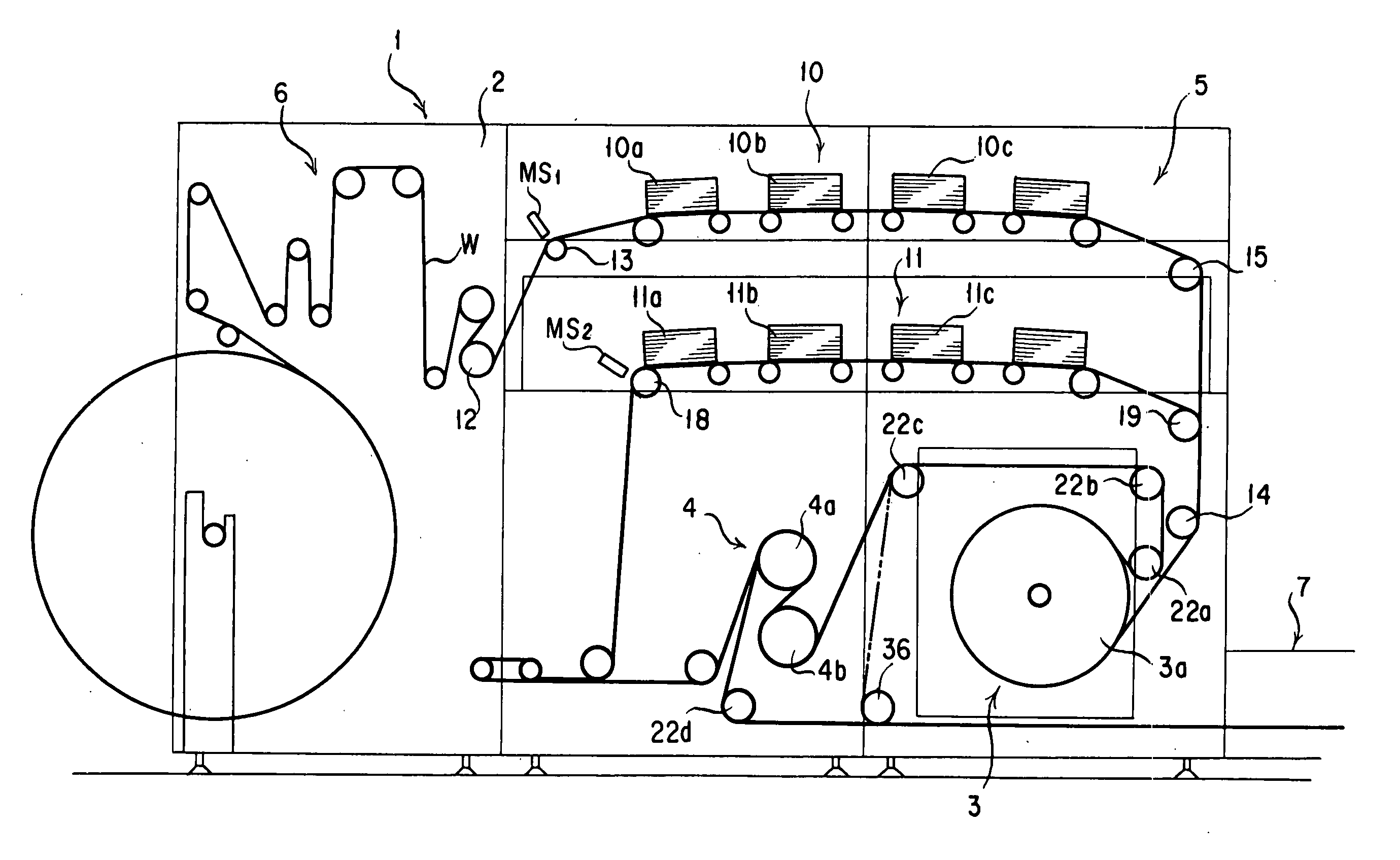
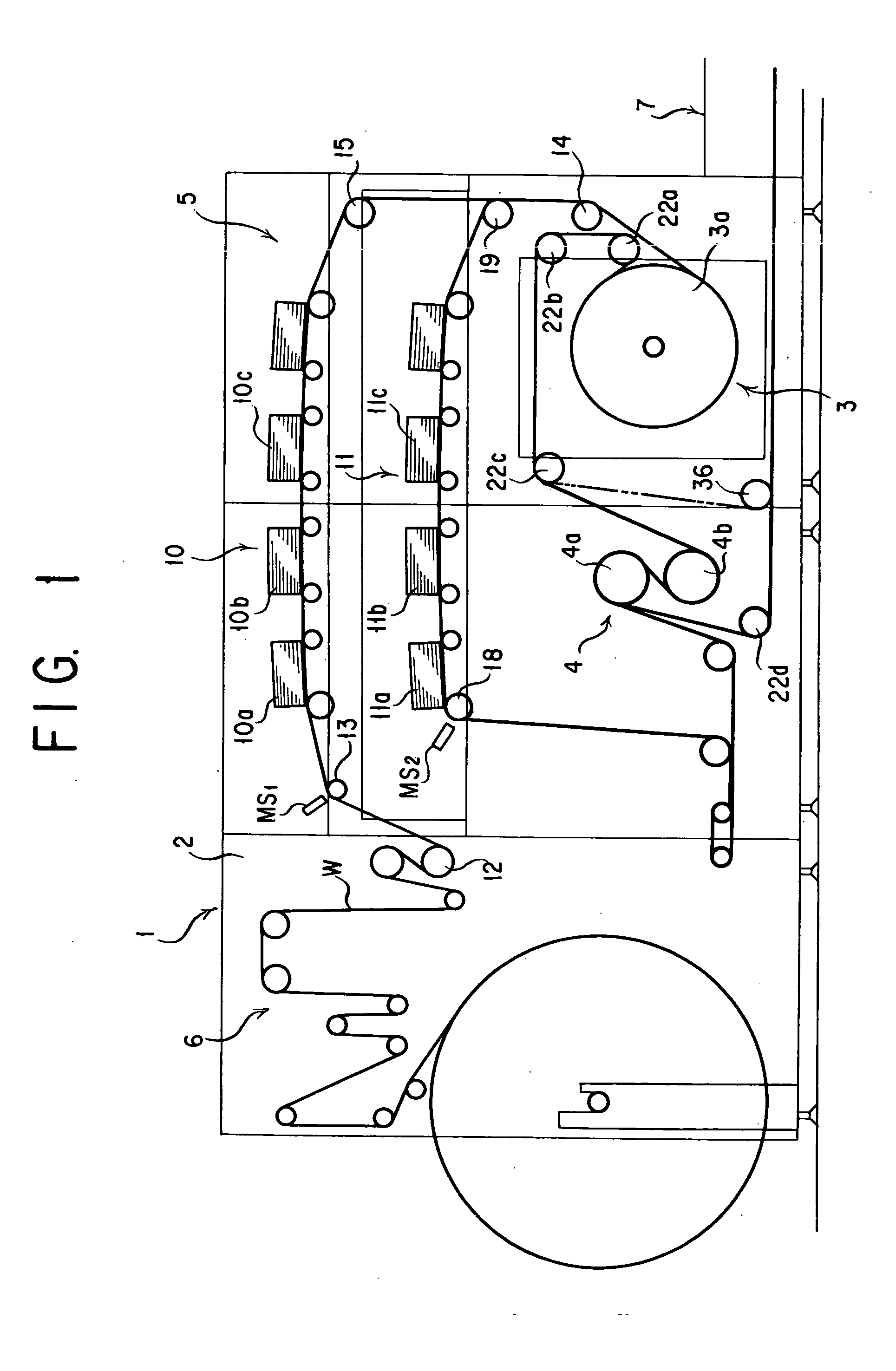
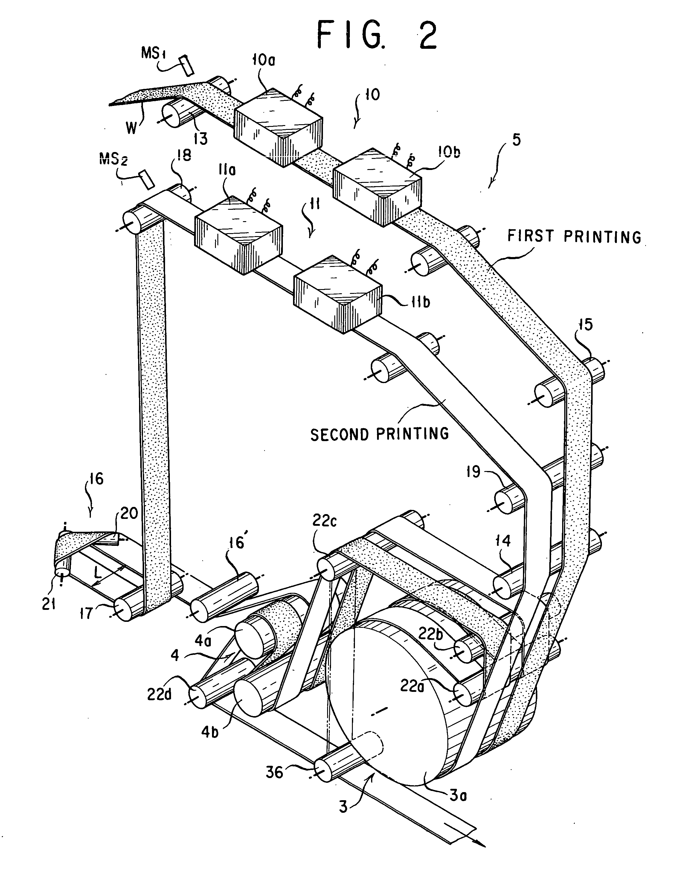
[0020]FIGS. 1 and 2 show a printing apparatus 1 for printing both front and back sides of continuous paper with a time difference, using aqueous ink by means of ink jet printer equipment. The printing apparatus 1 is provided below a machine frame 2 with a dryer section 3 and a cooling roller unit 4 and above them with a printing section 5. Continuous paper W supplied traveling laterally from a paper feeder 6 disposed at one side (left hand side in this form of implementation) is printed on its front and back sides through the printing section 5 sequentially with a time difference, dried through the dryer section3, cooled through the cooling roller unit 4 and discharged from a discharge section 7 disposed at the other side (right hand side in this form of implementation) of the machine frame 2. Continuous paper W is then taken up onto...


PUM


Abstract

To allow continuous paper to be printed a plurality of times with a time difference by ink jet printer equipment and dried each time of printing while preventing condensation from occurring on an ink discharge surface of print head at and after the second time of printing, there is provided a printing apparatus comprising: a plurality of trains of printing units each of which has print heads arranged along a direction in which a continuous sheet of paper travels and which are arranged parallel to one another as shifted mutually in position in a direction of width of the continuous sheet of paper; a dryer section in which a plurality of continuous sheets of paper from the plural printing unit trains can travel as mutually shifted in position in a direction of width of the continuous sheet of paper; a cooling roller unit disposed downstream of the dryer section and having a cooling roller on which the plurality of continuous sheets of paper from the dryer section can be wound as mutually shifted in position in a direction of width of the continuous sheet of paper; and a turnover unit disposed between the cooling roller unit and a train of printing units for shifting the continuous sheet of paper in position into a direction of its width while reversing the direction in which it travels.

Description

BACKGROUND OF THE INVENTION[0001]1. Technical Field[0002]The present invention relates to a printing apparatus in which continuous paper is printed at least twice with a time difference on one or both of its front and back faces by ink jet printer equipment and is dried as it is passed through a dryer section at each time of printing.[0003]2. Description of the Prior Art[0004]A printing apparatus in which continuous paper is printed twice with a time difference on both of its front and back sides by ink jet printer equipment and is dried as it is passed through a dryer at each time of printing has already been applied for in a patent application filed by the present applicant (see JP 2004-224002 A).[0005]There is also a printing apparatus which is equipped with a heater body for heating continuous paper and in which a moisture condensation or absorbing member is provided in the vicinity of an ink discharge nozzle in a print head to prevent a printing trouble from occurring from cond...

Claims


Application Information

Patent Timeline
IPC IPC(8): B41J3/60B41J15/04B41J2/01
CPCB41J3/543B41J3/60B41J15/165B41J11/002B41J15/04B41J11/0015
Inventor IZAWA, HIDEOISHIKAWA, AKIRA
Owner MIYAKOSHI PRINTING MACHINERY
Why Eureka
Try Eureka