

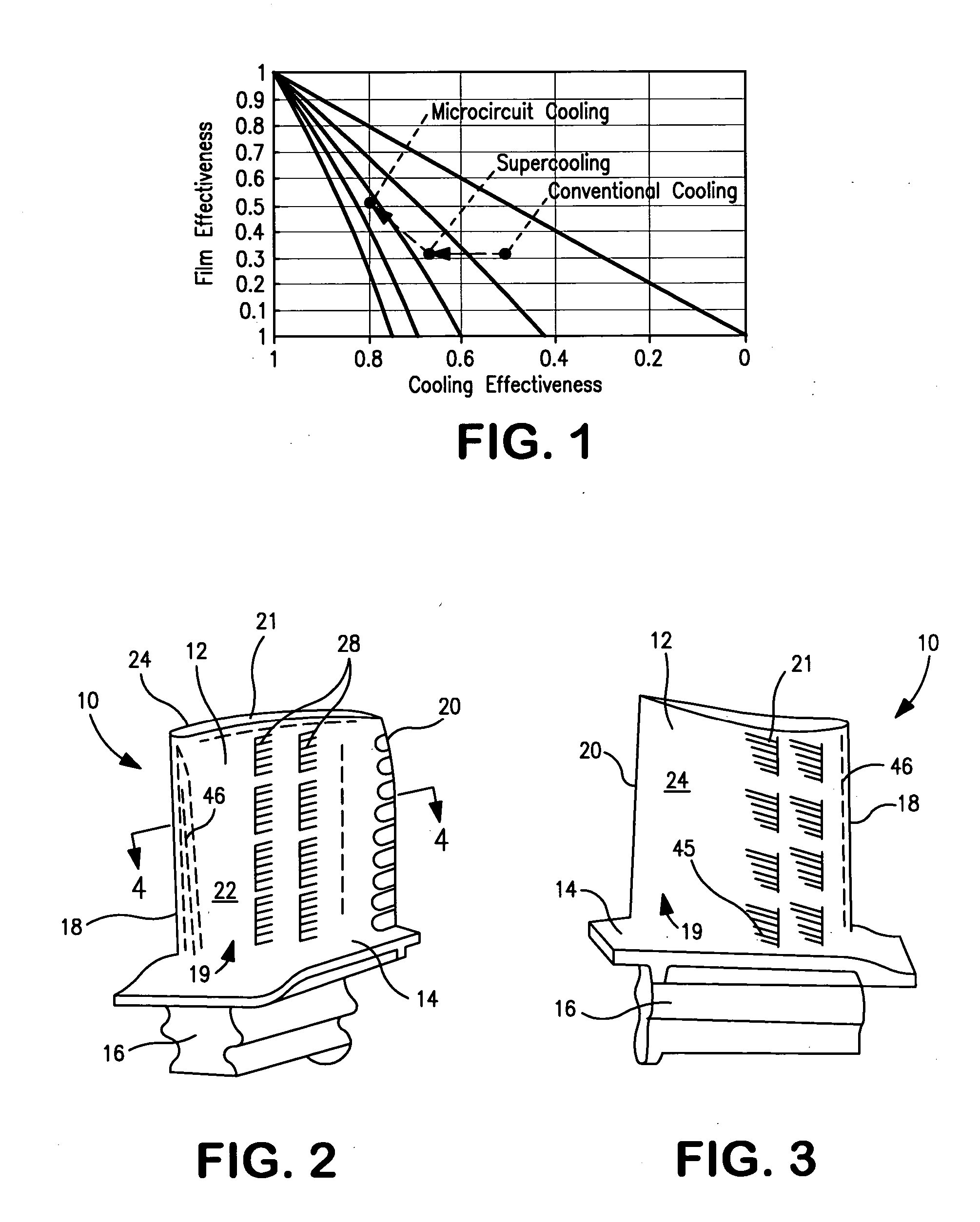
Microcircuit cooling with an aspect ratio of unity
- Summary
- Abstract
- Description
- Claims
- Application Information
AI Technical Summary
Benefits of technology
Problems solved by technology
Method used
Image

Examples
Embodiment Construction
)
[0021] Referring now to FIGS. 2 and 3, there is shown a turbine engine component 10, such as turbine blade or vane. The component 10 has an airfoil portion 12, a platform 14, and an attachment portion 16. The airfoil portion 12 has a leading edge 18, a trailing edge 20, a pressure side 22, a suction side 24, a root 19, and a tip 21. The turbine engine component 10 may be formed from any suitable material known in the art, such as a nickel based superalloy.
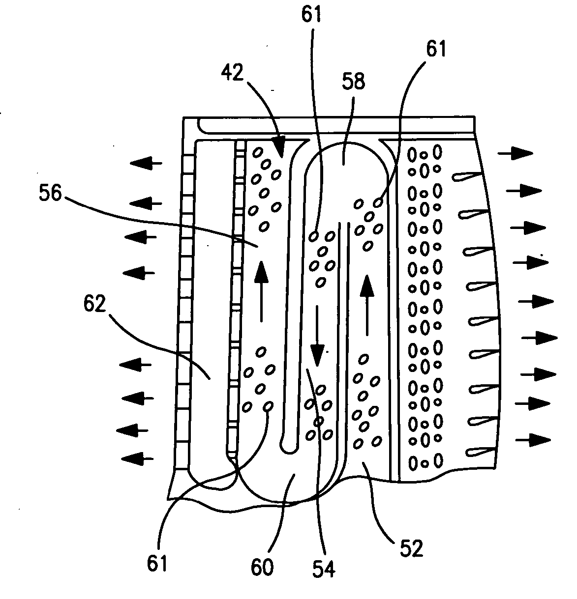
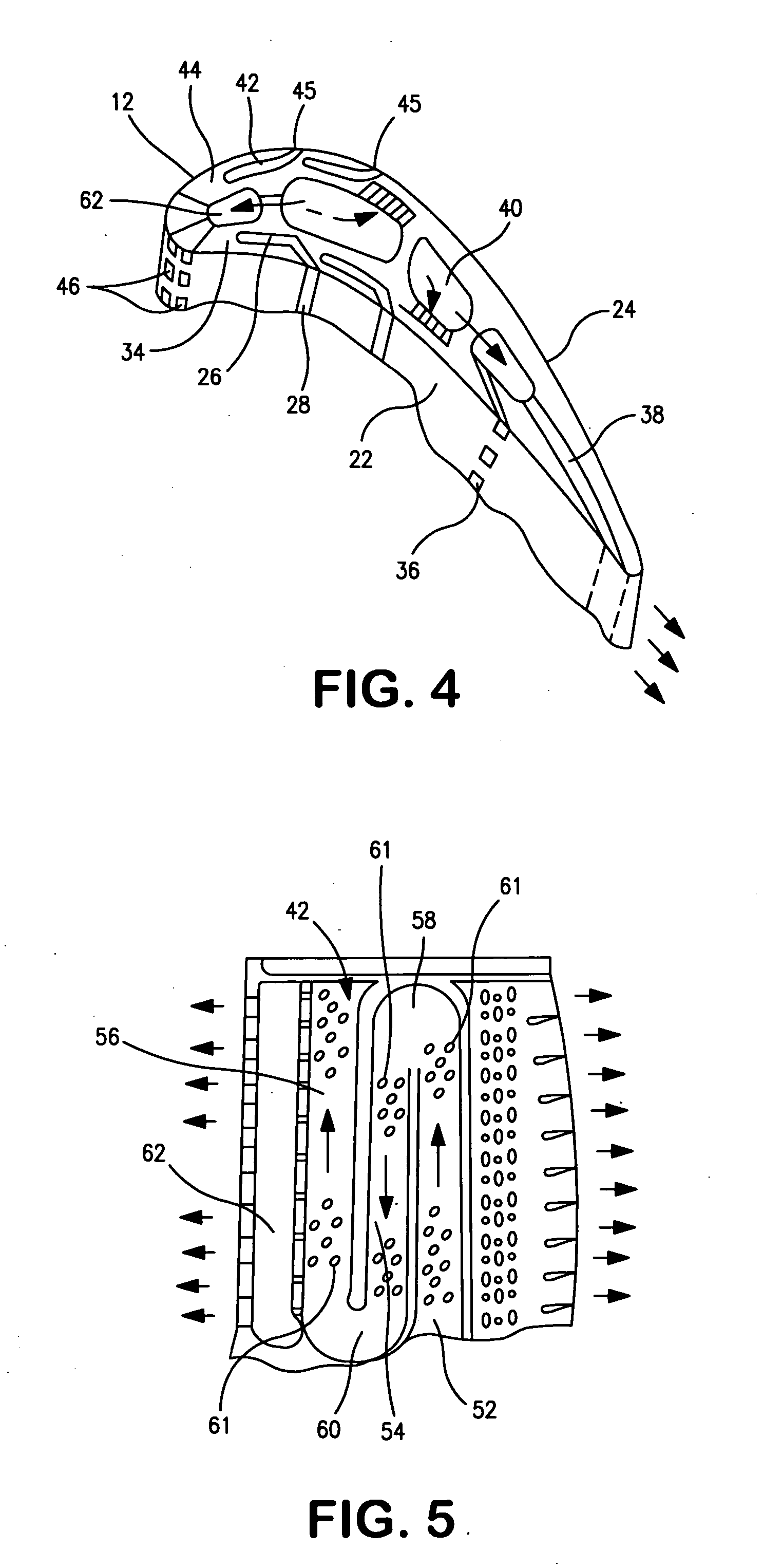
[0022] Referring now to FIG. 4, there is shown a cooling system for a turbine engine component 10. The cooling system includes one or more pressure side cooling circuits or passages 26 having film cooling slots 28. The cooling circuit(s) or passage(s) 26 and the film cooling slot(s) 28 associated with each circuit or passage 26 may be formed by using a refractory metal core 30 having one or more tabs 32. As can be seen from FIG. 4, the cooling circuit(s) or passage(s) 26 are preferably formed within a wall 34 of the airfoil porti...
PUM
 Abstract
Description
Claims
Application Information