Selectively routing air within an electronic equipment enclosure

a technology of electronic equipment and air routing, which is applied in the field of racks and cabinets, can solve the problems that the air flow through the mounted equipment (typically, computer servers) may exceed the flow capacity of the floor tile, and achieve the effect of preventing recirculation

Inactive Publication Date: 2007-07-26
CHATSWORTH PROD INC
View PDF99 Cites 106 Cited by
  • Summary
  • Abstract
  • Description
  • Claims
  • Application Information

AI Technical Summary

Benefits of technology

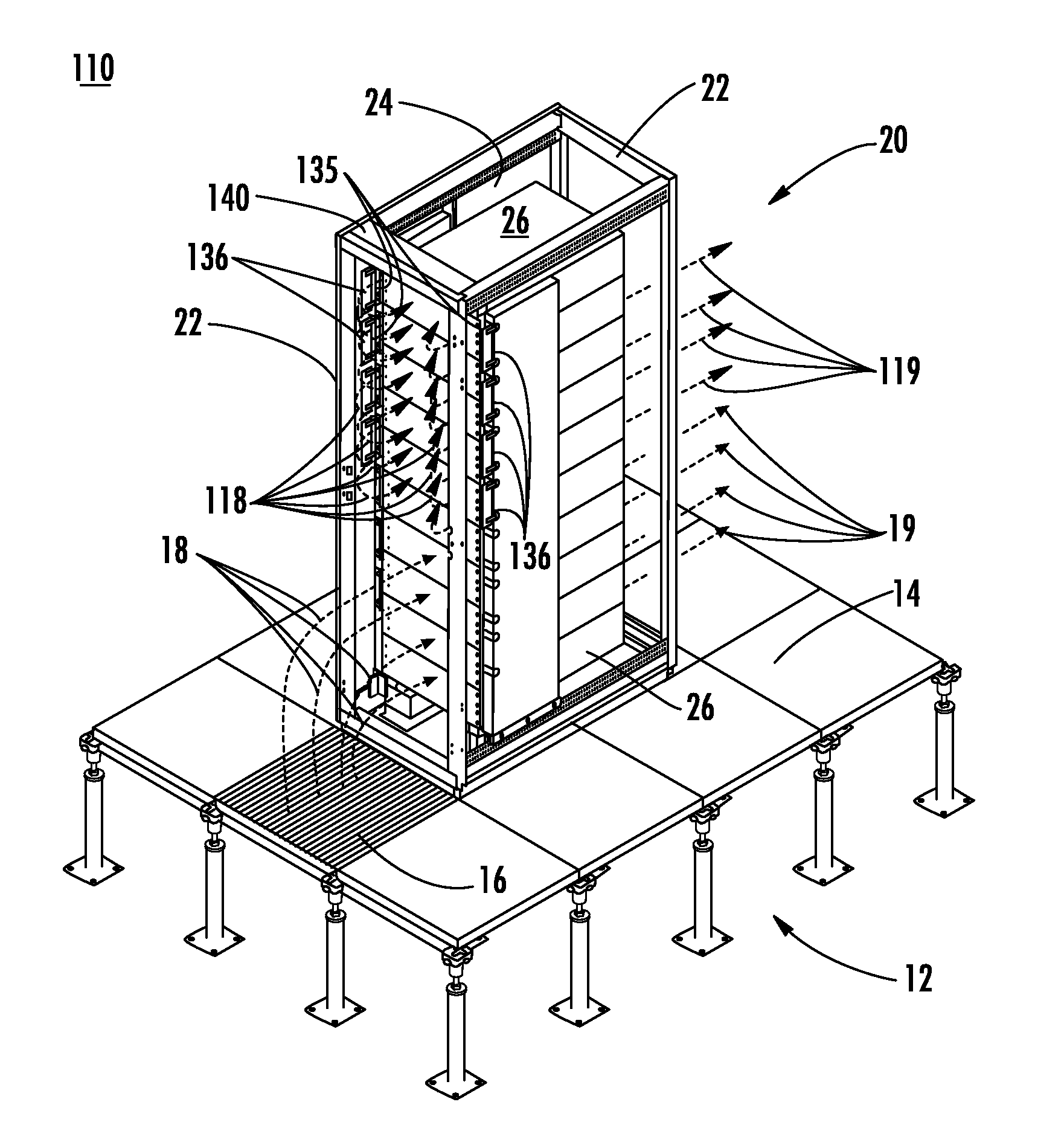
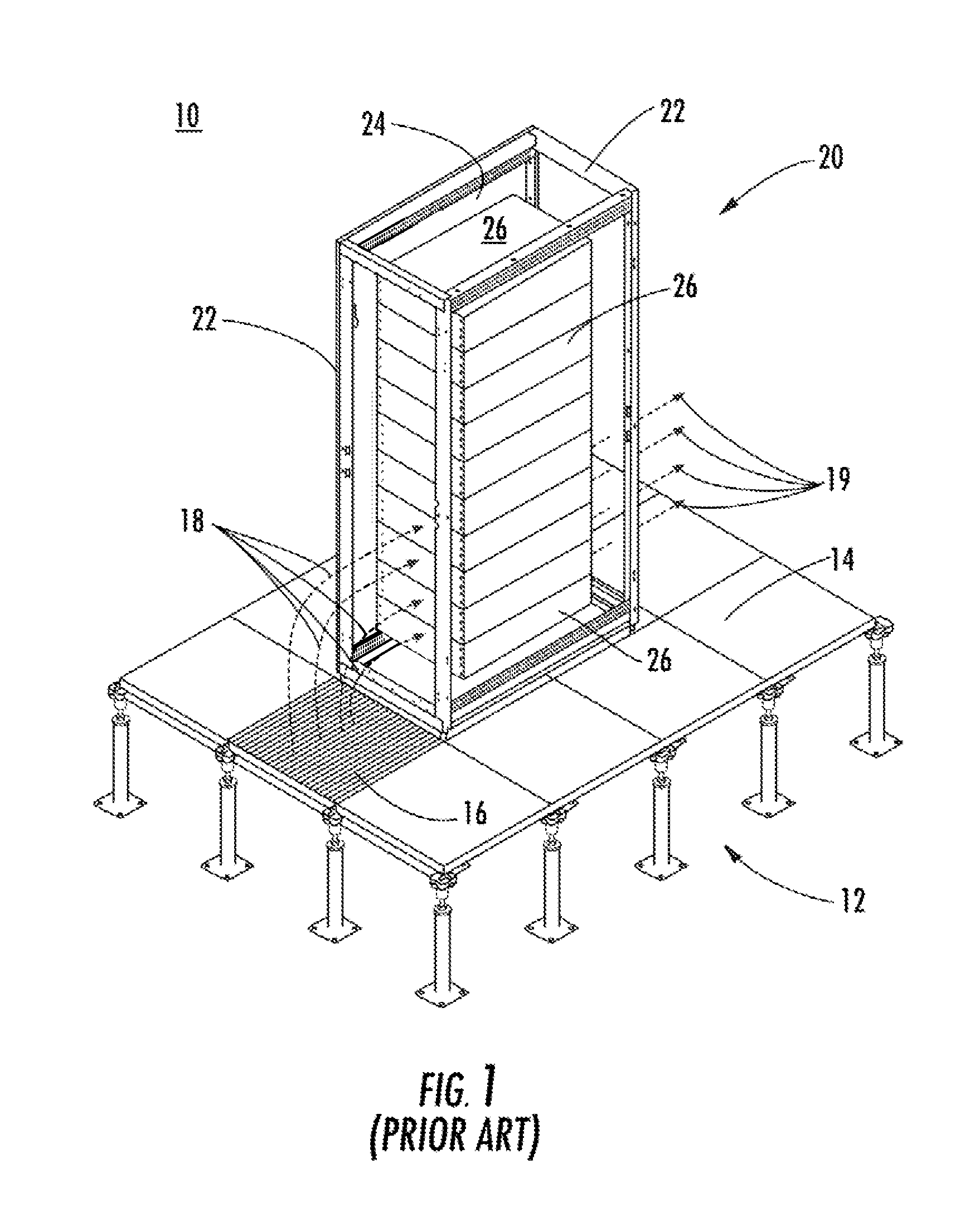
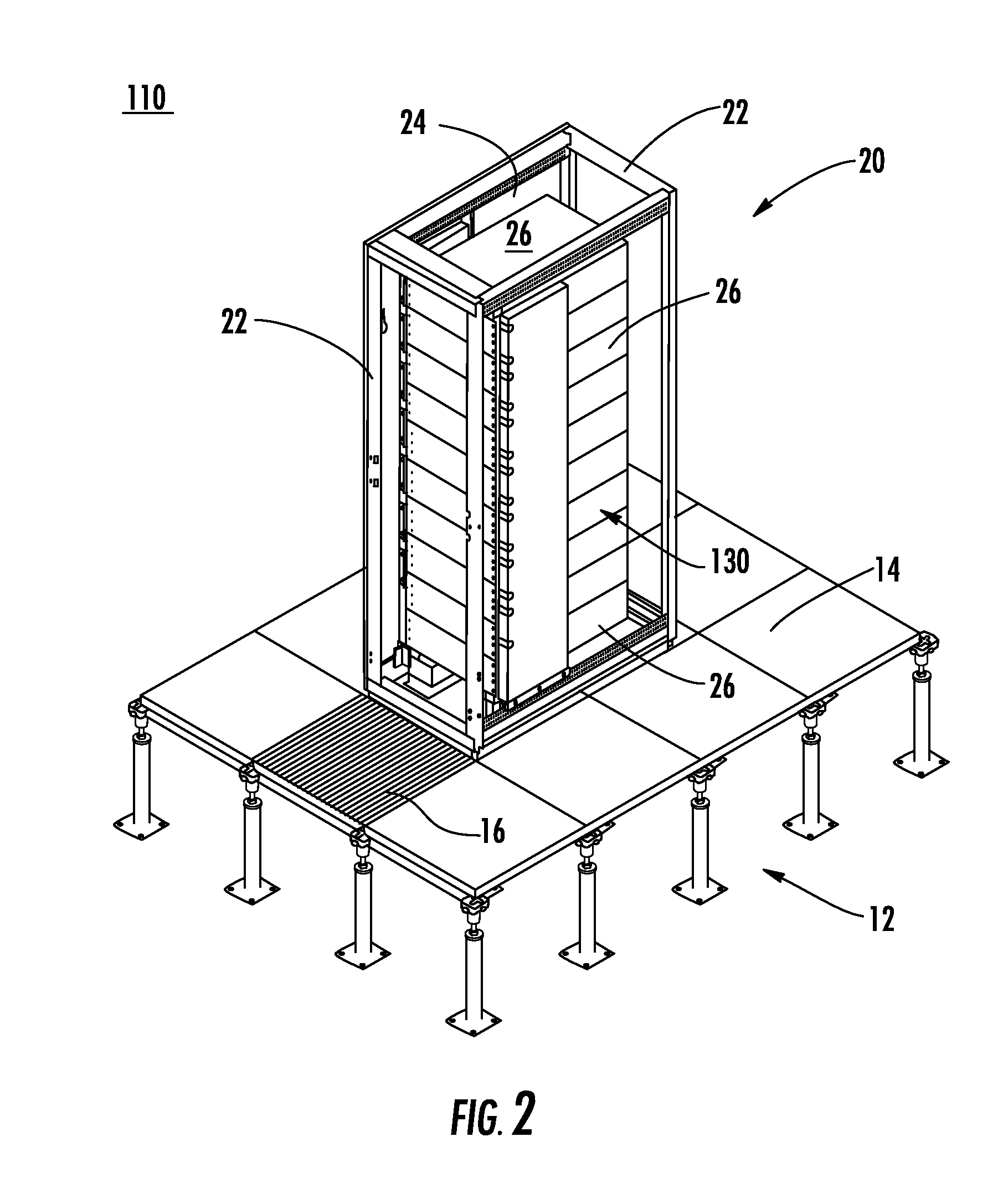
[0016]Typical datacenter cooling strategies rely on perforated floor tiles placed directly in front of the enclosure. Particularly in densely populated enclosures with high flow requirements, the air flow through the mounted equipment (typically, computer servers) may exceed the flow capacity of the floor tile. In such applications, the equipment mounted in the lower portion of the enclosure will have air which is considerably colder than the air available at the upper equipment mounting positions. The air duct of the present invention may be used in these situations to route cold air above the lower equipment and directly to the intake region of the upper Rack Mount Unit (“RMU”) locations. Because the intake for the air duct is located beneath the enclosure and additional air flow is routed along the sides of the equipment, the net flow capacity to an enclosure may be increased by using the duct in conjunction with a perforated tile located in front of the enclosure.
[0023]In a feature of this aspect, the internal air duct is dimensioned to occupy the entire space between the side of the electronic equipment and the side of the enclosure to prevent recirculation of air around the side of the electronic equipment. In another feature of this aspect, the electronic equipment enclosure installation includes a second internal air duct mounted laterally adjacent a side of the electronic equipment opposite the side where the first internal air duct is disposed such that the second internal air duct fits in a space between the second side of the electronic equipment and a second side of the enclosure. With regard to this feature, the second internal air duct is dimensioned to occupy the entire space between the second side of the electronic equipment and the second side of the enclosure to prevent recirculation of air around the second side of the electronic equipment.
[0029]In a feature of this aspect, routing air from beneath the enclosure to an upper portion of the enclosure includes routing air from beneath the enclosure through a collector and into a riser and further routing through the riser to a port disposed therein and arranged in the upper portion of the enclosure, and wherein routing air to the electronic equipment includes routing air from the port to the electronic equipment. In accordance with this feature, the method further comprises configuring the collector such that an interior thereof is in fluid communication with an interior of the riser, such that air may flow freely from the beneath the enclosure through the collector to the riser.
[0030]In a fifth aspect of the invention, a method of preventing recirculation around electronic equipment disposed in an electronic equipment enclosure comprises installing and arranging at least one riser within the enclosure in such a manner that recirculation is prevented.

Problems solved by technology

Particularly in densely populated enclosures with high flow requirements, the air flow through the mounted equipment (typically, computer servers) may exceed the flow capacity of the floor tile.

Method used


Image

  • Selectively routing air within an electronic equipment enclosure
  • Selectively routing air within an electronic equipment enclosure
  • Selectively routing air within an electronic equipment enclosure

Examples


Embodiment Construction

[0051]As a preliminary matter, it will readily be understood by one having ordinary skill in the relevant art (“Ordinary Artisan”) that the present invention has broad utility and application. Furthermore, any embodiment discussed and identified as being “preferred” is considered to be part of a best mode contemplated for carrying out the present invention. Other embodiments also may be discussed for additional illustrative purposes in providing a full and enabling disclosure of the present invention. Moreover, many embodiments, such as adaptations, variations, modifications, and equivalent arrangements, will be implicitly disclosed by the embodiments described herein and fall within the scope of the present invention.

[0052]Accordingly, while the present invention is described herein in detail in relation to one or more embodiments, it is to be understood that this disclosure is illustrative and exemplary of the present invention, and is made merely for the purposes of providing a f...


PUM


Abstract

A method of cooling electronic equipment mounted in an enclosure includes routing air from beneath the enclosure to an upper portion of the enclosure, selectively routing air to electronic equipment mounted in the upper portion of the enclosure, and exhausting heated air from the electronic equipment to an enclosure outlet. In addition, preventing recirculation includes installing and arranging an internal air duct within an enclosure in such a manner that recirculation is prevented, and balancing air temperature around an enclosure includes using an internal air duct.

Description

CROSS-REFERENCE TO RELATED APPLICATION[0001]The present application is a U.S. nonprovisional patent application of, and claims priority under 35 U.S.C. § 119(e) to, U.S. Provisional Patent Application No. 60 / 743,148, filed Jan. 20, 2006, which provisional patent application is incorporated by reference herein.COPYRIGHT STATEMENT[0002]All of the material in this patent document is subject to copyright protection under the copyright laws of the United States and of other countries. The copyright owner has no objection to the facsimile reproduction by anyone of the patent document or the patent disclosure, as it appears in the Patent and Trademark Office patent file or records, but otherwise reserves all copyright rights whatsoever.BACKGROUND OF THE PRESENT INVENTION[0003]1. Field of the Present Invention[0004]The present invention relates generally to racks and cabinets for supporting computer and other electronic equipment, and, in particular, to air ducts for providing cool air to h...

Claims


Application Information

Patent Timeline
Patent Type & Authority Applications(United States)
IPC IPC(8): H05K5/00
CPCH05K7/20009
Inventor LEWIS, RICHARD EVANS
Owner CHATSWORTH PROD INC
Why Eureka
Try Eureka