Reversible transmission mechanism

a transmission mechanism and reverse transmission technology, applied in mechanical devices, differential gearings, gearings, etc., can solve the problems of naturally complicated structure of reverse transmission mechanisms and insufficient compactness of reverse transmission mechanisms, and achieve the effect of simple structur

Inactive Publication Date: 2007-07-26
NTN CORP
View PDF3 Cites 8 Cited by
  • Summary
  • Abstract
  • Description
  • Claims
  • Application Information

AI Technical Summary

Benefits of technology

[0005]An object of the present invention is to provide a reversible transmission mechanism of the above-described type which is made up of fewer parts, and simple in structure.

Problems solved by technology

In the former type, because the input and output shafts have to be disposed parallel to each other while being sufficiently spaced from each other, this reversible transmission mechanism is not sufficiently compact.
This reversible transmission mechanism is naturally complicated in structure.

Method used


Image

  • Reversible transmission mechanism
  • Reversible transmission mechanism
  • Reversible transmission mechanism

Examples


Embodiment Construction

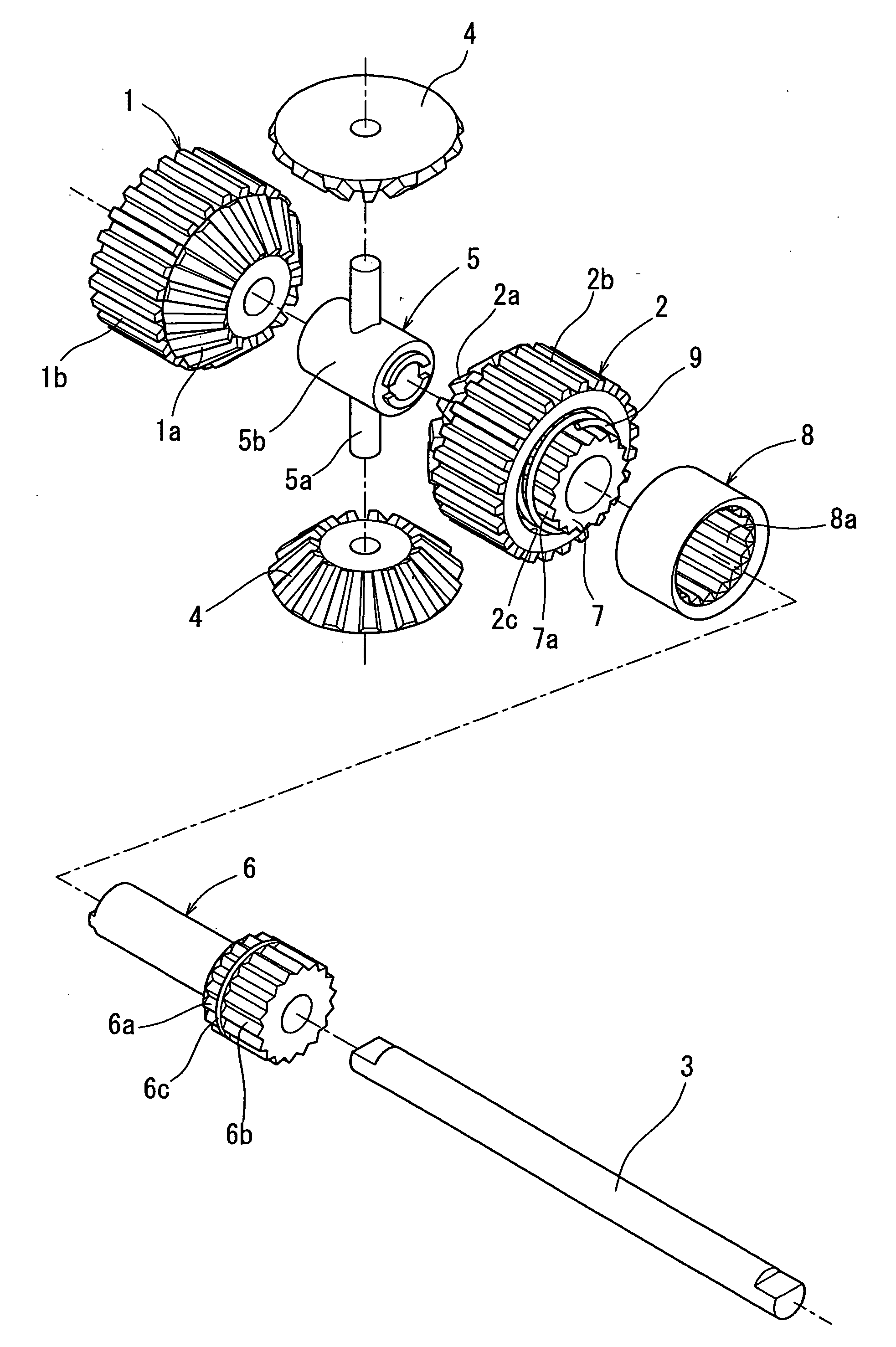
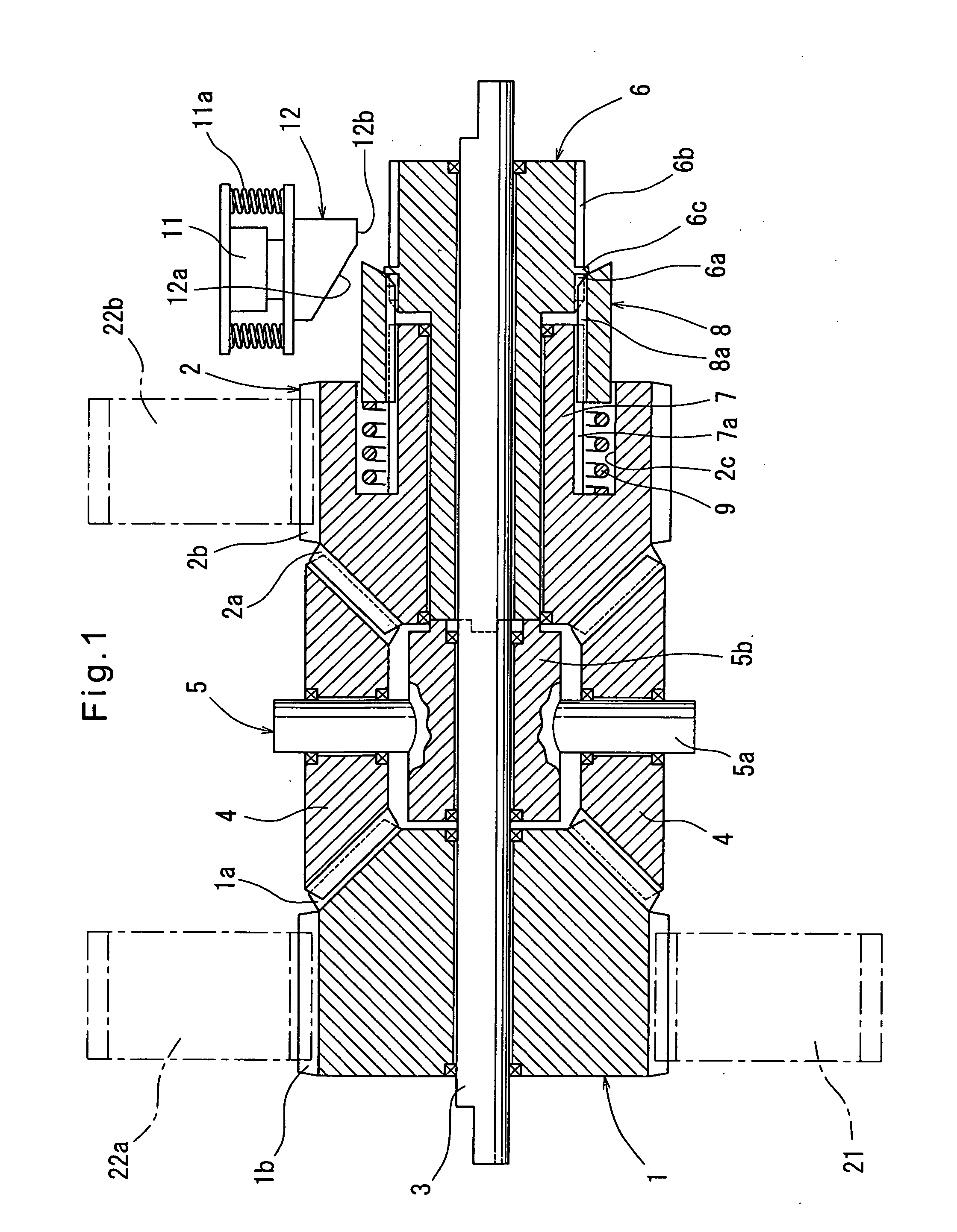
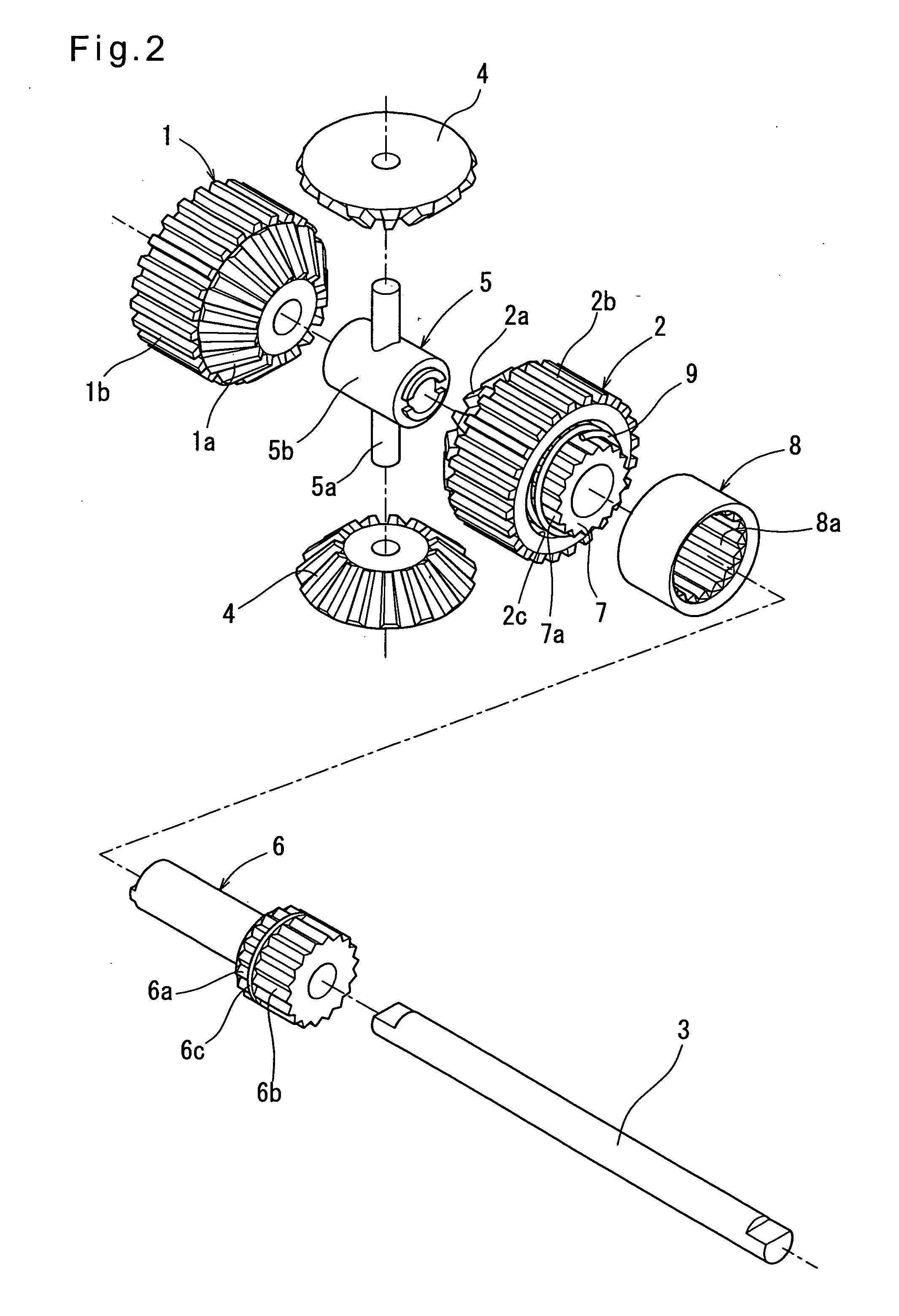
[0027]Now referring to the drawings, the embodiments of the present invention are described. FIGS. 1 to 4 show the reversible transmission mechanism according to the first embodiment, which includes, as shown in FIGS. 1 and 2, an input member 1 and an output member 2 that are rotatably mounted on a common fixed shaft 3 and carry bevel gears 1a and 2a, respectively, that axially face each other. A first shaft member 5 is disposed between the input and output members 1 and 2. The first shaft member 5 comprises a tubular portion 5b rotatably fitted around the fixed shaft 3, and two shafts 5a fixed to and extending from the tubular portion 5b in directions opposite to each other and perpendicular to the fixed shaft 3. A planetary bevel gear 4 is rotatably mounted on each shaft 5a so as to mesh with the bevel gears 1a and 2a. The input member 1 and the output member 2 carry an input spur gear 1b and an output spur gear 2b on their outer surfaces, respectively. Idler gears 22a and 22b mes...


PUM


Abstract

A reversible transmission mechanism includes an input member rotatable about a fixed shaft and having a bevel gear, a first shaft member rotatable about the fixed shaft and having a shaft portion extending perpendicular to the fixed shaft, and a second shaft member rotatable about the fixed shaft and rotationally fixed to the first shaft member. An output member is rotatably mounted around the second shaft member and has a bevel gear at one end thereof axially facing the bevel gear of the input member. A planetary bevel gear is rotatably mounted around the shaft portion of the first shaft member so as to mesh with the bevel gears of the input and output members. The second shaft member is selectively coupled to and uncoupled from the output member by a clutch. When the second shaft member is uncoupled from the output member, the rotation of the second shaft member is stopped by a brake.

Description

BACKGROUND OF THE INVENTION[0001]The present invention relates to a reversible transmission mechanism which is capable of converting the rotation of an input member to the rotation of an output member in either direction.[0002]It is required that some of a large number of rollers used in copiers and printers be rotatable in either direction in order to e.g. print both sides of sheets. Rotation is transmitted to such rollers through reversible transmission mechanisms, which include two types, i.e. one including spur gears through which rotation is transmitted to the output shaft, and one including bevel gears through which rotation is transmitted to the output shaft. In the former type, because the input and output shafts have to be disposed parallel to each other while being sufficiently spaced from each other, this reversible transmission mechanism is not sufficiently compact. The latter type is not compact either, because the input and output shafts have to be arranged to extend p...

Claims


Application Information

Patent Timeline
Patent Type & Authority Applications(United States)
IPC IPC(8): F16H48/06
CPCF16H48/08F16H48/24F16H48/295F16H48/30Y10T74/19372F16H2048/204F16H2048/346Y10T74/19498F16H48/34
Inventor TAKADA, SEIICHI
Owner NTN CORP
Why Eureka
Try Eureka