Flexible support member with high pushability

Inactive Publication Date: 2007-07-26
CORDIS CORP
View PDF20 Cites 2 Cited by
  • Summary
  • Abstract
  • Description
  • Claims
  • Application Information

AI Technical Summary

Benefits of technology

[0007] It is an object of the invention to provide a delivery device having a sufficient degree of flexibility, yet posse

Problems solved by technology

However, care must be taken to insure that flexibility is not excessive, for if flexibility is too great, the structural integrity of the coiled member (and hence, the delivery device) could be adversely affected.
For example, if flexibility of the coiled member is too great, the device m

Method used


Image

  • Flexible support member with high pushability
  • Flexible support member with high pushability
  • Flexible support member with high pushability

Examples


Example

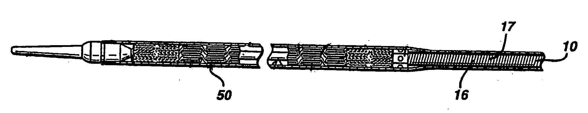
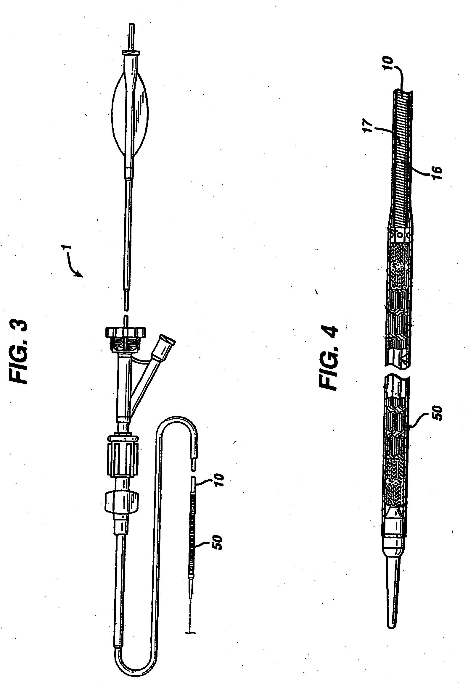
[0020] Reference is made to U.S. Pat. No. 6,773,446, which shares the assignee of the present application, and which disclosure is incorporated herein by reference. Referring now to the figures wherein like numerals indicate the same element throughout the views, there is shown in FIGS. 3 and 4 a medical device delivery device 1, which specifically is a delivery device for self-expanding stents. Device 1 comprises inner and outer coaxial tubes. The inner tube is called the shaft 10 and the outer tube is called the sheath 40. A self-expanding stent 50 is located within the outer sheath, wherein the stent makes frictional contact with the outer sheath and the shaft is disposed coaxially within a lumen of the stent. Shaft 10 has a body portion 16, wherein at least a portion of 16 is made from a flexible coiled member 17.

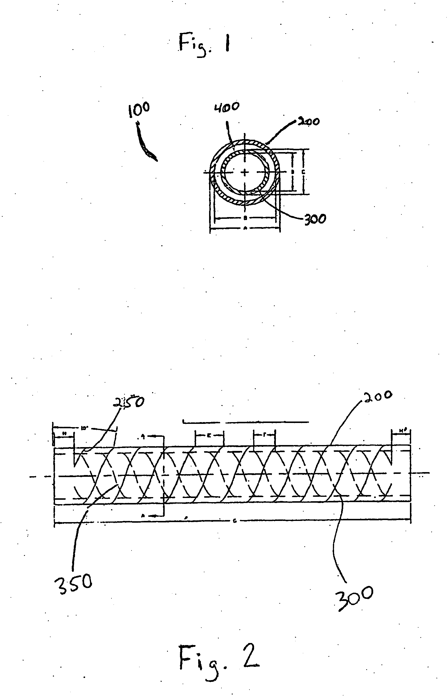
[0021] The coaxial tube-in a tube arrangement described herein can be employed as the coiled member portion of the shaft of a medical implant delivery device, which by...


PUM


Abstract

The present invention is directed to the field of medical devices, and in particular, to a medical device for delivering a medical implant to a patient's body, the device having a pushing member that is constructed of tubes arranged coaxially.

Description

FIELD OF THE INVENTION [0001] The present invention is directed to the field of medical devices, and in particular, a system (and components thereof) for delivering and deploying medical implants, such as stents for use in treating disorders such as vascular disease. BACKGROUND OF THE INVENTION [0002] A medical implant, such as a stent, is commonly used as a tubular structure left inside the lumen of a duct or vessel to relieve an obstruction. Stents are inserted into the lumen in a non-expanded form and are then expanded in situ by self-expanding action or by other means, such as by applying a force extending radially outward to the interior stent walls. Stents may be expanded during or just after balloon angioplasty. [0003] A stent-type medical implant is ordinarily delivered and deployed via a delivery system. Such delivery systems may have an outer sheath forming an elongated tubular member having distal and proximal ends and an inside and outside diameter, and may also include ...

Claims


Application Information

Patent Timeline
IPC IPC(8): A61F11/00
CPCA61F2/95
Inventor FERNANDEZ, JOSEHARRIES, HEATHER ANN BARTHOLF
Owner CORDIS CORP
Why Eureka
Try Eureka