Slitting tool

a technology of cutting tools and cutting blades, applied in the field of cutting blades, can solve the problems of tools presenting one or more difficulties to the user

Active Publication Date: 2007-08-02
MEDTRONIC INC
View PDF37 Cites 41 Cited by
  • Summary
  • Abstract
  • Description
  • Claims
  • Application Information

AI Technical Summary

Problems solved by technology

However, these tools present one or more difficultie

Method used


Image

  • Slitting tool
  • Slitting tool
  • Slitting tool

Examples


Embodiment Construction

[0013] The following detailed description is exemplary in nature and is not intended to limit the scope, applicability, or configuration of the invention in any way. Rather, the following description provides practical illustrations for implementing exemplary embodiments of the present invention.

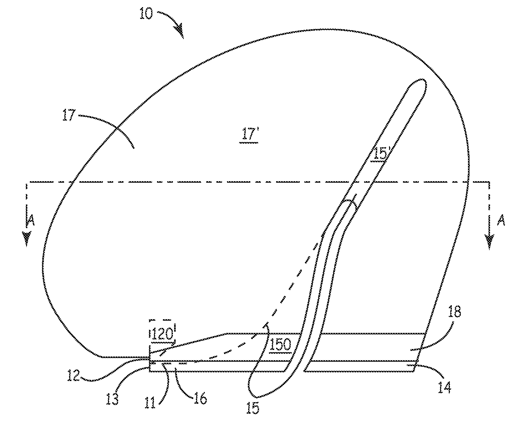
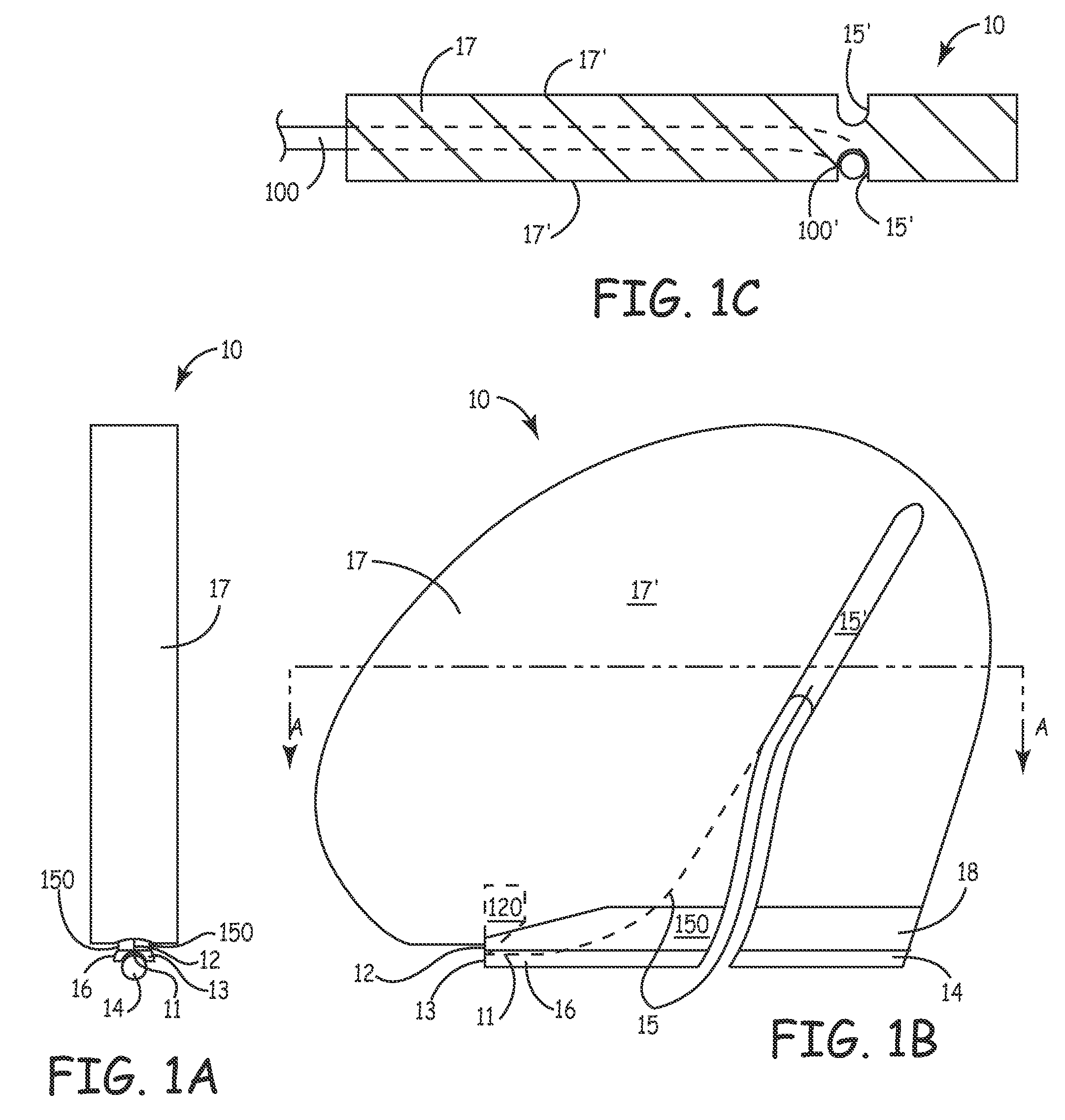
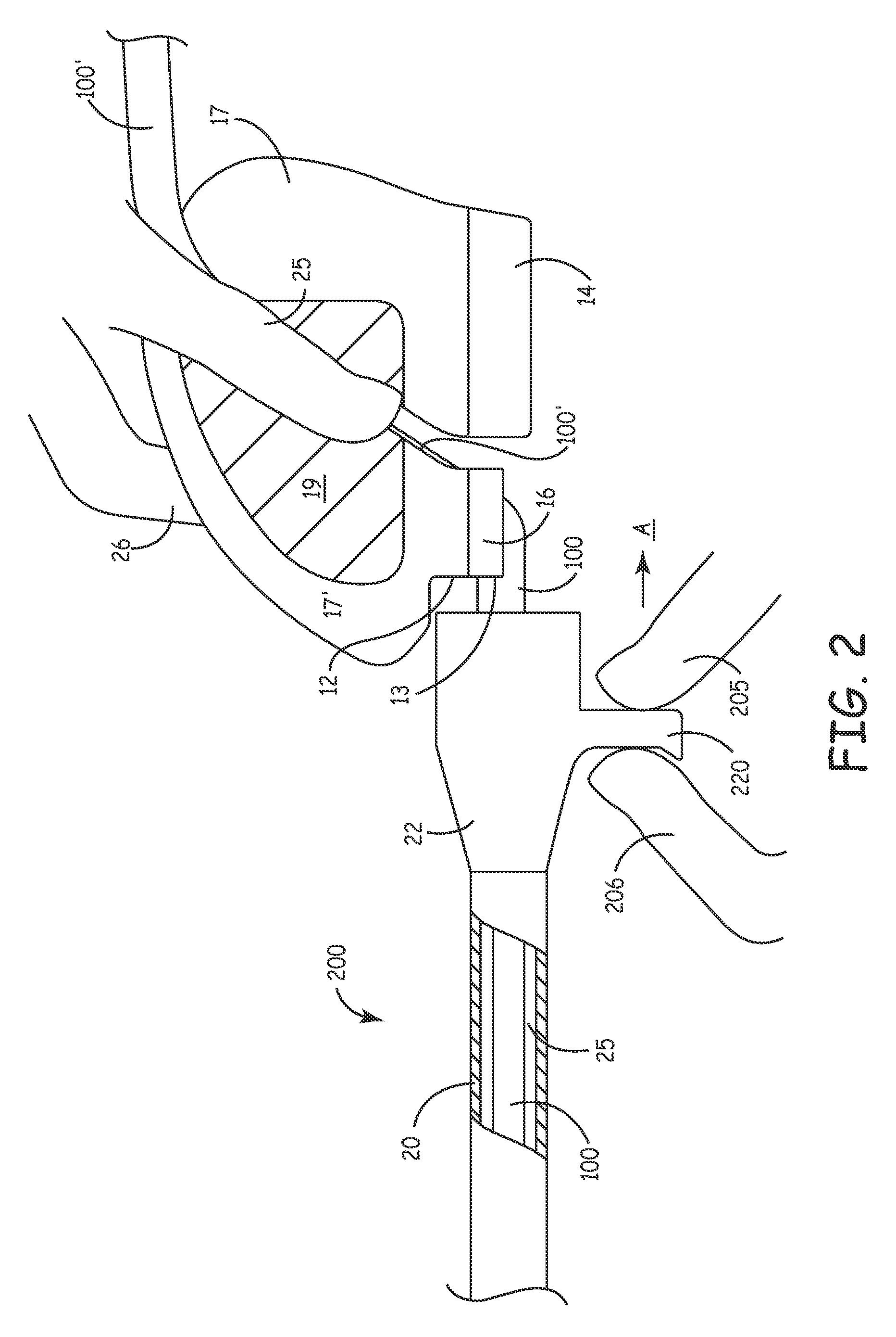
[0014] FIGS. 1A-B are an end view and a side plan view, respectively, of a slitting tool 10, according to one embodiment of the present invention; and FIG. 1C is a section view through line A-A of FIG. 1B. FIGS. 1A-C illustrate tool 10 including a nose portion 16, a handle portion 17, a slitting edge 12 extending between nose portion 16 and handle portion 17, a longitudinally extending tail portion 14, and a passageway 15 disposed between nose portion 16 and tail portion 14, and extending upward into handle portion 17. FIGS. 1A-B further illustrate nose portion 16 including a lower surface 11 and a leading edge 13. According to the illustrated embodiment, slitting edge 12 is part of a metal...


PUM

PropertyMeasurementUnit
Lengthaaaaaaaaaa
Thicknessaaaaaaaaaa
Diameteraaaaaaaaaa

Abstract

A tool for slitting an elongate sheath from about an elongate member that is disposed within a longitudinally extending lumen of the sheath includes a longitudinally extending tail portion projecting rearward of a slitting edge and a nose portion of the tool; a lower surface of the nose portion is disposed beneath the slitting edge for engaging a portion of the elongate member. The tail portion of the tool, approximately aligned with the sheath lumen when the lower surface engages the elongate member and a leading edge of the nose portion is within the sheath lumen, is sized to fit within the sheath lumen after the sheath is slit by the slitting edge. A passageway between the nose portion and the tail portion allows a proximal segment of the elongate member to bend away from the tail portion when the elongate member is engaged by the nose portion.

Description

FIELD OF THE INVENTION [0001] The present invention pertains to slitting tools and more particularly to slitting tools facilitating removal of an elongate sheath or catheter from about an elongate member disposed therein. BACKGROUND OF THE INVENTION [0002] Sheaths, or catheters, are commonly used in minimally invasive medical procedures, for example, to provide a pathway for the introduction of elongate medical devices into the vascular system of a patient. Many medical devices, introduced in such a manner, through a lumen of the sheath, are intended to indwell within the patient for a prolonged period, for example, extending from a number of days to many years. After the indwelling medical device has been inserted within the lumen of the sheath, for positioning within the patient, it is desirable to remove the sheath from the patient without dislodging the indwelling device. [0003] A number of slitting tools, known to those skilled in the art, are used to remove sheaths from about ...

Claims


Application Information

Patent Timeline
IPC IPC(8): B26B3/00B26B29/00
CPCA61F2/4455A61M2025/0675A61F2/4611A61F2002/2835A61F2002/30235A61F2002/30332A61F2002/30405A61F2002/30581A61F2002/30601A61F2002/30617A61F2002/4623A61F2002/4629A61F2220/0025A61F2220/0033A61F2230/0069A61F2250/0097A61M25/0662A61F2/4601Y10T83/0605A61F2/4603
Inventor GOODE, JOHNSON E.DRAKE, RON A.
Owner MEDTRONIC INC
Why Eureka
Try Eureka