Clamp

a technology of clamps and lugs, which is applied in the direction of sleeve/socket joints, mechanical equipment, machines/engines, etc., can solve the problems of engine vibration, expansion and contraction of both tubes and clamps, and wasting a portion of installation energy in deforming lugs, etc., to achieve the effect of convenient opening

Active Publication Date: 2007-08-02
NORMA US HOLDING LLC
View PDF14 Cites 25 Cited by
  • Summary
  • Abstract
  • Description
  • Claims
  • Application Information

AI Technical Summary

Benefits of technology

[0007] The clamp is positioned around the tubes to be connected, and the fastener is tightened to tighten the clamp around the connection. The fastener may be tightened from an open position, when the lugs are not touching, to a closed position, when the thick portions of the lugs are touching. The fastener may be tightened further to a third position—even after the thick portions of the lugs touch—so that the thin portions of the lugs move closer to one another. The ability to further tighten the clamp after the thick portions of the legs touch allows the first embodiment of the clamp to attain a tight fit with the tubes.
[0008] In a second embodiment of the clamp, the collar includes one or more hinge areas formed in the collar. For improved sealing, the hinge area allows space to position a gasket between the clamp and the tubes, including flared or flanged tubes. The hinge area also allows the clamp to be easily opened enough to slide over the tube flare or flanges during installation. .

Problems solved by technology

Stresses arise from engine vibrations, exhaust gas pressure, exhaust system weight, road bumps, etc.
The temperature variations often cause expansion and contraction of both the tubes and the clamps.
In this case, some portion of the installation energy was wasted in deforming the lugs, instead of pulling both ends of the collar 12 together.
Thus, the clamp often times does not generate enough force to seal the connection.

Method used


Image

  • Clamp
  • Clamp
  • Clamp

Examples


first embodiment

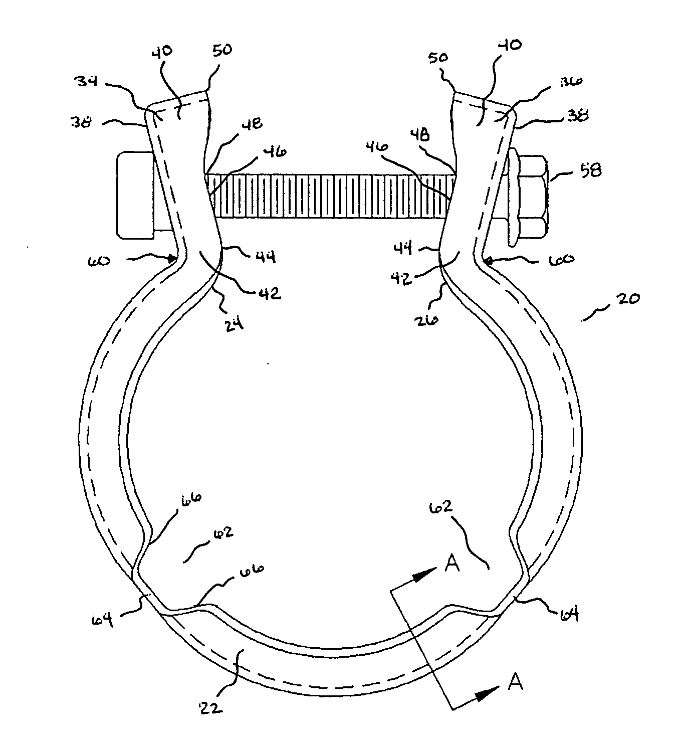
[0024] The clamp 20 is positioned around the tubes to be connected, and the fastener 58 is tightened to tighten the clamp around the connection. The fastener 58 may be tightened from an open position OP (FIG. 3), when the lugs 34, 36 are not touching, to a closed position CP (FIG. 4), when the thick portions 40 of the lugs are touching. The fastener 58 may be tightened further to a third position—even after the thick portions 40 of the lugs touch—so that the thin portions 42 of the lugs 34, 36 move closer to one another (as shown by arrows 60 in FIG.2). The ability to further tighten the clamp 20 after the thick portions 40 of the lugs 34, 36 touch allows the clamp to attain a tight fit with the tubes.

[0025] The terms “collar” and “tube” are used through this disclosure and shall mean “tubes” and “collars” of all shapes including but not limited to circular, polygonal and other shaped “tubes” and “collars.” Those of skill in the art will recognize that the material of the clamp may ...

second embodiment

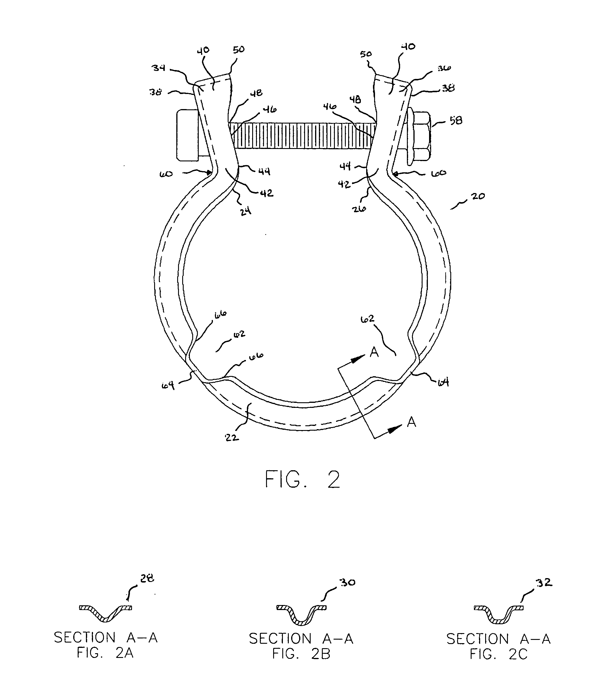
[0026]FIGS. 2, 3 and 4 also show features of the clamp 20 in which the collar 22 includes one or more hinge areas 62 formed in the collar. The hinge areas 62 define a space between the clamp 20 and the tube that can be used to attach a gasket to the clamp or tube, allowing for improved sealing between tubes, including those that are flared or flanged. The hinge areas 62 also provide flexibility to allow the clamp 20 to be opened sufficiently to easily fit over the maximum diameter of the tubes being connected without disengaging the nut and bolt.

[0027] The hinge areas 62 may have a variety of shapes and, as shown in the embodiment of FIGS. 2, 3 and 4, the hinge areas are defined by hinge walls that form two angled planes 66 connected by a flat plane 64. Note that although FIGS. 2, 3 and 4 show clamps having hinge areas 62, the first embodiment need not include hinge areas or gaskets. The clamp has been shown and discussed as used with one or more tubes, including non-flared or non-f...


PUM


Abstract

The present invention pertains to a clamp that includes a collar. The collar has first and second ends from which first and second lugs extend. Each of the first and second lugs has a thick portion and a thin portion, and the lugs are connected by a fastener. The clamp is positioned around tubes, and the fastener is tightened to tighten the clamp around the connection. The fastener may be tightened from an open position OP, when the lugs are not touching, to a closed position CP, when the thick portions of the lugs are touching. The fastener may be tightened further to a third position, so that the thin portions of the lugs move closer to one another. The clamp may also include a hinge area in which a gasket seal may be attached to the clamp or one of the tubes.

Description

BACKGROUND OF THE INVENTION [0001] The present invention relates to clamps used to connect tubes and, in particular, flared or flanged tubes. [0002] Clamps are often used to connect tubes. For example, most vehicles incorporate several tubes in their exhaust system that are connected by clamps. Tubes from the engine block, the catalytic converter and the tail pipe are connected to one another by clamps. The clamps and tubes are exposed to a wide range of temperature variations and stresses. The temperature varies from ambient, at vehicle start-up, to near exhaust gas temperature when operating under heavy loads. Stresses arise from engine vibrations, exhaust gas pressure, exhaust system weight, road bumps, etc. [0003] The temperature variations often cause expansion and contraction of both the tubes and the clamps. The clamps must securely connect the tubes to prevent leakage while withstanding the temperature variations and stresses. As shown in FIG. 1, clamps 10 of the prior art c...

Claims


Application Information

Patent Timeline
Patent Type & Authority Applications(United States)
IPC IPC(8): F16L23/00
CPCF01N13/1811F16L21/065F16L23/08
Inventor MA, RUFEILIEDTKE, DAN
Owner NORMA US HOLDING LLC
Why Eureka
Try Eureka