Locating Technique and Apparatus using an Approximated Dipole Signal

a dipole signal and approximate technology, applied in the direction of subaqueous/subterranean adaption, using reradiation, instruments, etc., can solve the problem of disadvantageous features

Inactive Publication Date: 2007-08-02
MERLIN TECH INC
View PDF13 Cites 26 Cited by
  • Summary
  • Abstract
  • Description
  • Claims
  • Application Information

AI Technical Summary

Problems solved by technology

As will be described below, this feature is considered as being disadvantageous based on signal decay characteristics and in view of further discoveries that are brought to light herein.

Method used


Image

  • Locating Technique and Apparatus using an Approximated Dipole Signal
  • Locating Technique and Apparatus using an Approximated Dipole Signal
  • Locating Technique and Apparatus using an Approximated Dipole Signal

Examples


Embodiment Construction

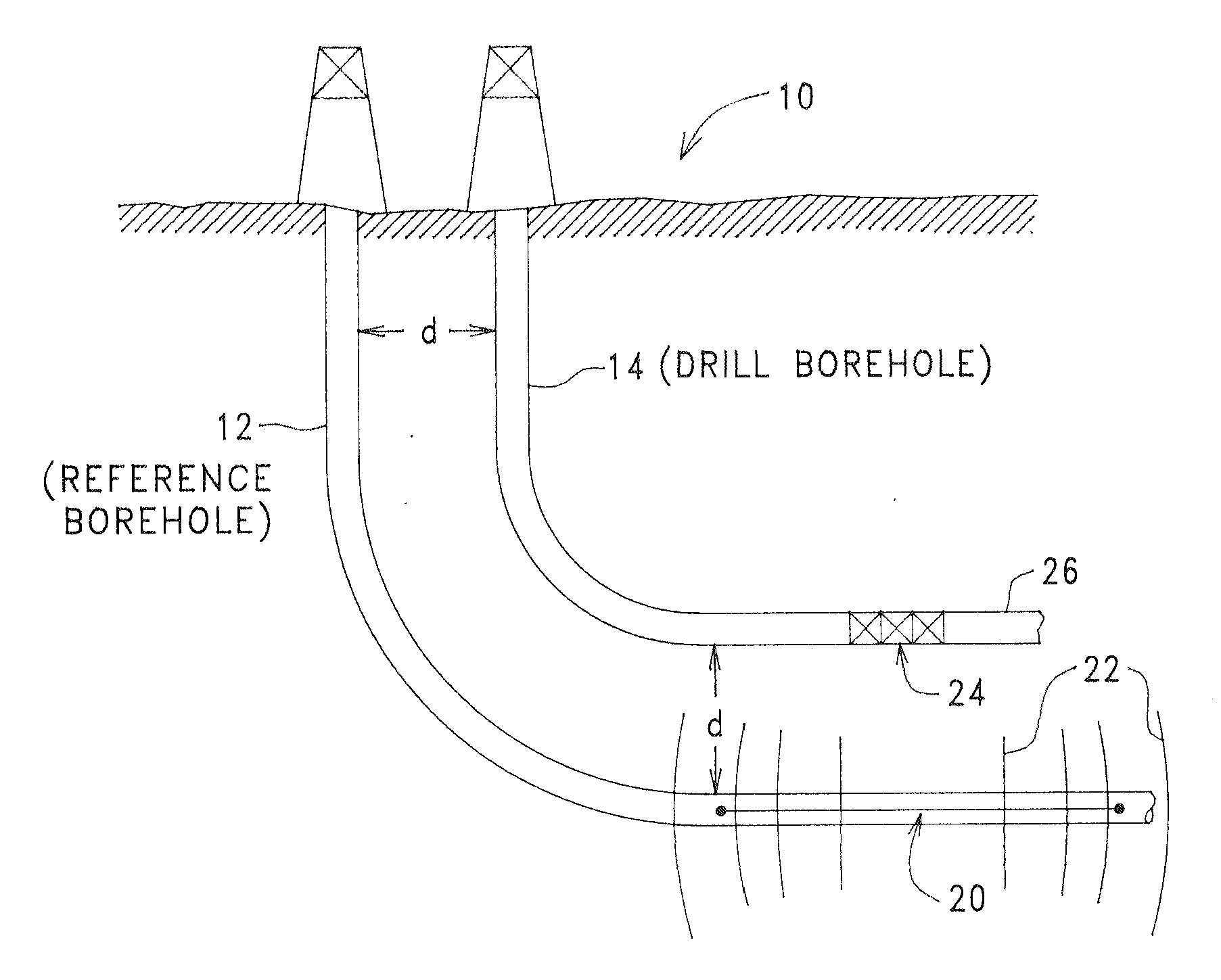
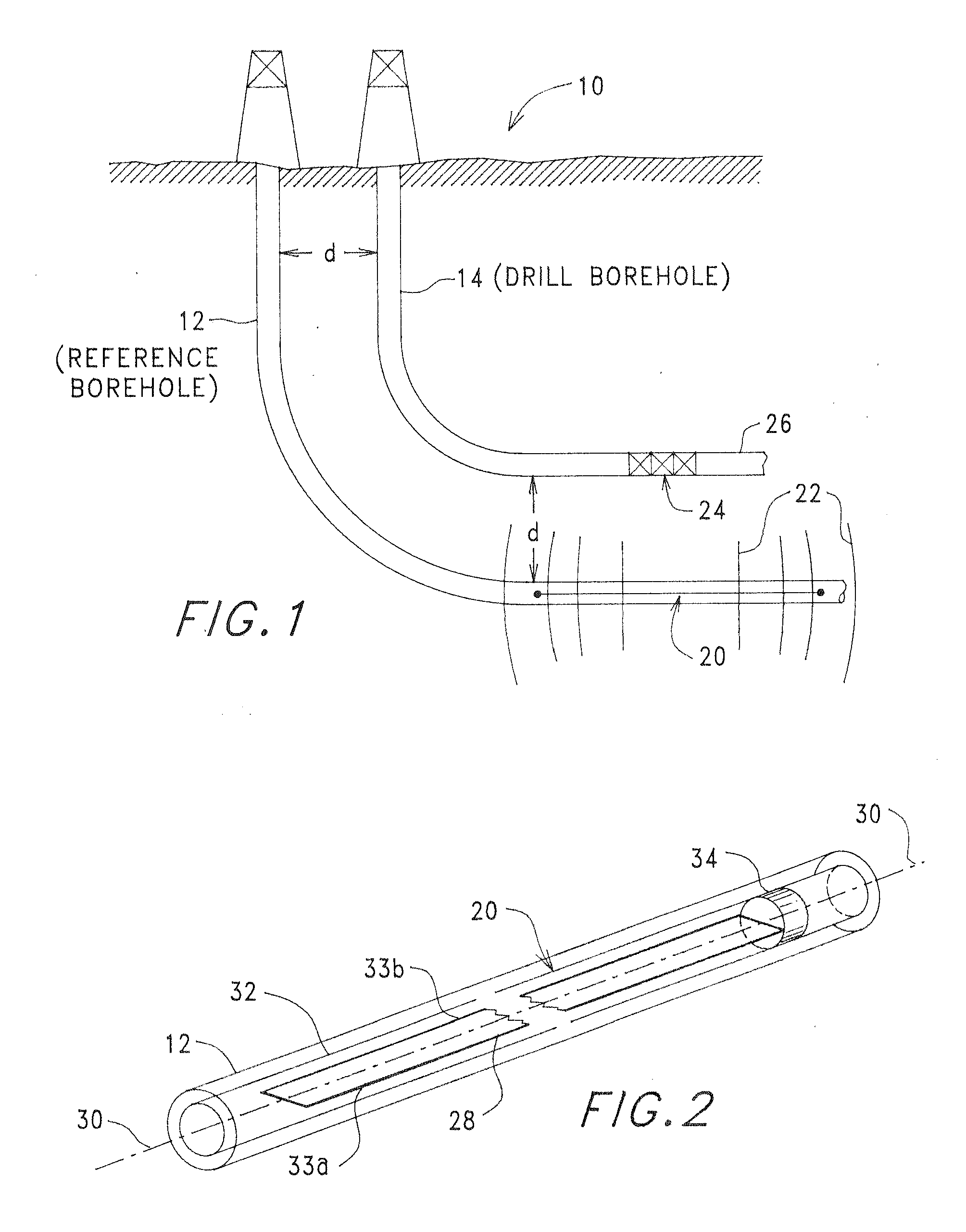
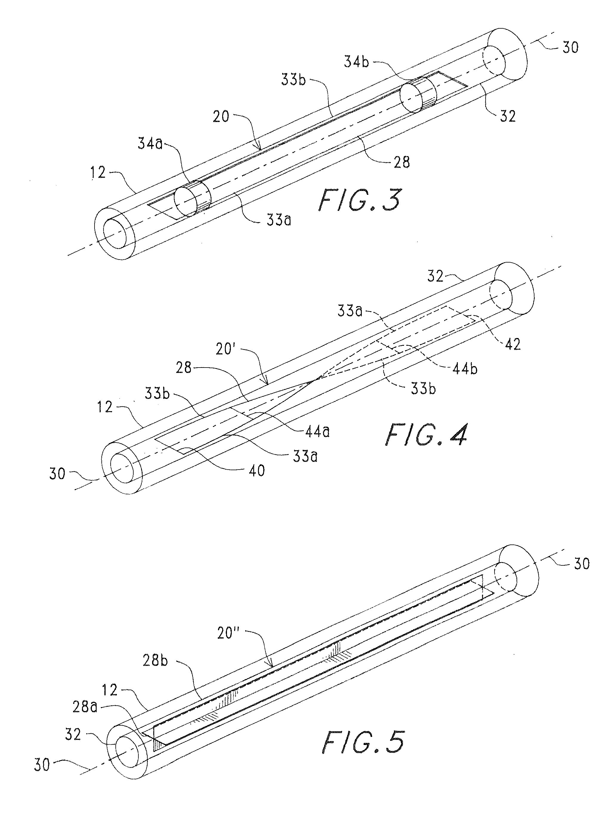
[0046] Turning now to the figures, wherein like reference numbers are used throughout the various figures to refer to like components, attention is immediately directed to FIG. 1 which illustrates a tracking and guidance system, generally indicated by the reference numeral 10, operating in first and second boreholes 12 and 14, respectively. It should be appreciated that FIG. 1 generally illustrates an operation wherein second borehole or well 14 is being drilled parallel to and above first borehole or well 12. Such wells formed having horizontally-extending, parallel sections are useful in certain types of resource extraction, as briefly described above. In particular, these wells are used in Steam Assisted Gravity Drainage (SAGD)™ operation. The present invention is well suited as an adjunct to SAGD for producing oil from heavy reserves such as from tar sand reservoirs during which steam is injected (not shown) into completed borehole 14 and, thereby, its surrounding tar sand to re...


PUM


Abstract

Location determination is performed using a transmitter including an elongated generally planar loop antenna defining an elongation axis. The elongation axis is positioned along at least a portion of a path. A magnetic field is then generated which approximates a dipole field. Certain characteristics of the magnetic field are then determined at a receiving position radially displaced from the antenna elongation axis. Using the determined certain characteristics, at least one orientation parameter is established which characterizes a positional relationship between the receiving position and the antenna on the path. The magnetic field may be transmitted as a monotone single phase signal. The orientation parameter may be a radial offset and / or an angular orientation between the receiving position and the antenna on the path. The antenna of the transmitter may be inserted into a first borehole to transmit the magnetic field to a receiver inserted into a second borehole.

Description

RELATED APPLICATION [0001] This is a continuation application of copending prior application Ser. No. 11 / 168,108, filed on Jun. 27, 2005; which is a continuation of application Ser. No. 10 / 097,224, filed on Mar. 12, 2002 and issued as U.S. Pat. No. 6,927,741 on Aug. 9, 2005; the disclosures of which are incorporated herein by reference. The present application also claims priority from U.S. Provisional Application Ser. No. 60,332,257, filed on Nov. 15, 2001.BACKGROUND OF THE INVENTION [0002] The present invention is related generally to the field of locating using an electromagnetic signal and, more particularly, to locating relative to a path using an electromagnetic locating signal. The apparatus and method of the present invention are highly advantageous with regard to determination of orientation relative to a target borehole, for example, in an operation intended to form another borehole arranged having a particular orientation with respect to the target borehole. [0003] A numb...

Claims


Application Information

Patent Timeline
Patent Type & Authority Applications(United States)
IPC IPC(8): H01Q7/00H01Q1/04H01Q9/28
CPCH01Q1/04G01V3/08H01Q9/28H01Q7/00
Inventor BRUNE, GUENTER W.MERCER, JOHN E.CHAU, ALBERT W.ZELLER, RUDOLF
Owner MERLIN TECH INC
Why Eureka
Try Eureka