Technique for lensless optical positioning

Inactive Publication Date: 2006-03-16
RAMER DAVID P
View PDF1 Cites 3 Cited by
  • Summary
  • Abstract
  • Description
  • Claims
  • Application Information

AI Technical Summary

Benefits of technology

[0010] It is an object of the present invention to provide

Problems solved by technology

However, disadvantages associated with PSD's include a slow response time, typically in the range of milliseconds, which is too slow for many applications, and a high noise floor, resulting in low sensitivity.
Thus, PSD's cannot be used in certain applications, such as laser guided munitions.
A

Method used


Image

  • Technique for lensless optical positioning
  • Technique for lensless optical positioning
  • Technique for lensless optical positioning

Examples


Embodiment Construction

)

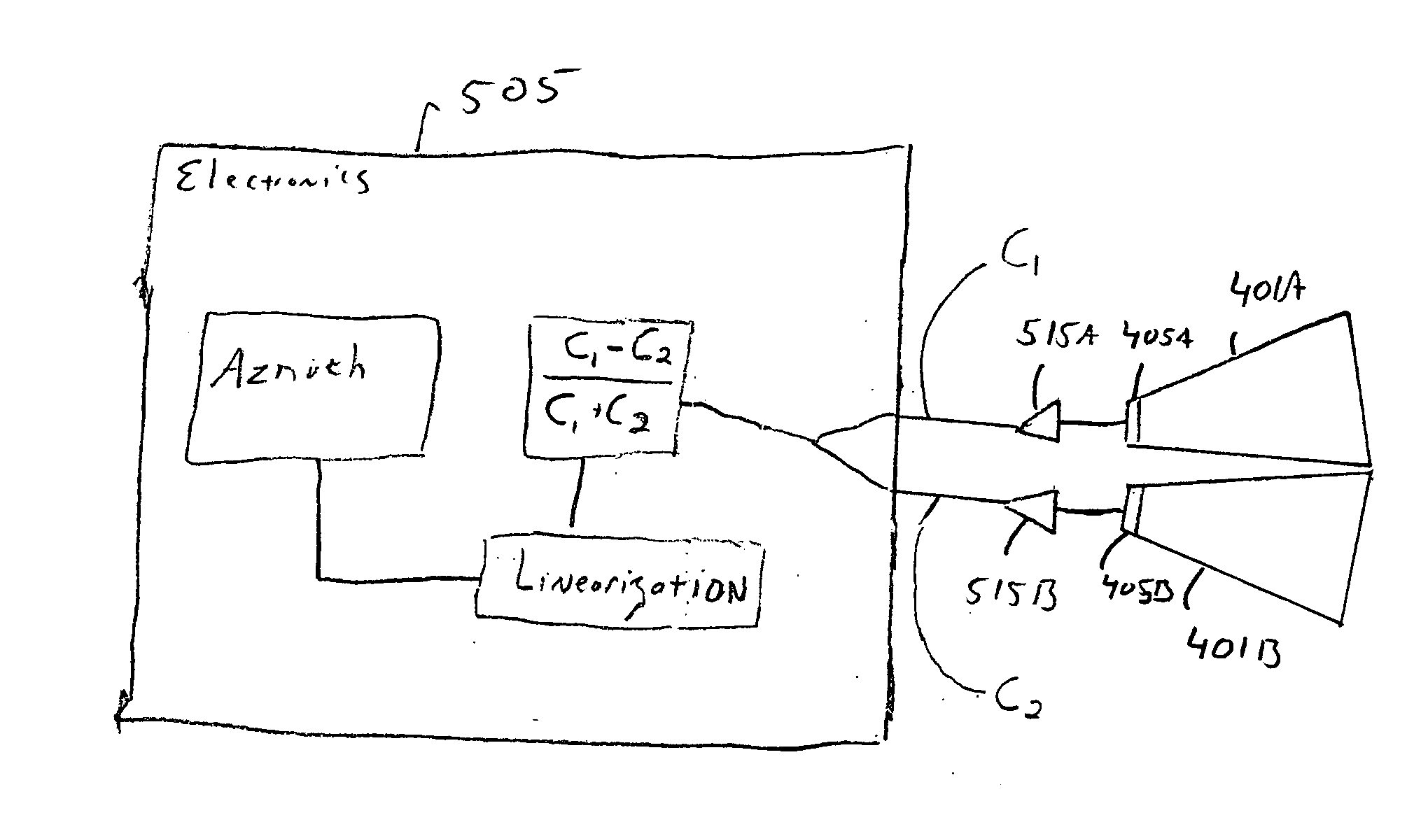
[0044] As shown in FIGS. 4A and 4B, optical position devices in accord with the present invention utilize non-imaging reflective optics. In a preferred embodiment of such a device, a cone 401 funnels light 205 to a detector 405. The cone 401 has a reflective inner surface that collects light from different directions to take advantage of the full sensitivity of detector 405. The cone may be, as desired, constructed of Mylar, plastic, glass, metal, or any substantially reflecting surface. For the best gain, substantially specular surfaces are preferred. However, quasi-specular surfaces may be used to smooth sensitivity irregularities. Even substantially diffuse surfaces could be used where high gain is not required. The cone may also be, as desired, constructed of a transparent solid with either Total Internal Reflection (TIR) or a reflector surface. A detector 405 is preferably a silicon and diode detector, though it could be any type detector capable of detecting light, such as, b...


PUM


Abstract

Systems and methods for determining a position of an object are provided by the present invention. Light is captured by at least one collector. Each collector has a first opening through which light enters that is larger than a second opening through which light exits. The exiting light is used by at least one light detector to generate signals. The position of the object is determined based upon the generated signals.

Description

FIELD OF THE INVENTION [0001] The present invention is related to optical positioning devices, and more particularly to a lensless optical positioning device. BACKGROUND OF THE INVENTION [0002] Optical position devices are well known. They are utilized in a variety of applications, including common automatic toilet flushers, video games, and sophisticated laser guided munitions. FIG. 1 is a simplified depiction of a laser guided munitions application. As shown, a laser beam 110 is aimed at a building 115 from an airplane 105. A missile 100 includes a seeker 120 that senses laser light 125 reflected from the building 115. The seeker 120 tracks the reflected laser light 125, guiding the missile to the building 115. [0003] There are two primary methods of optical position detection. One utilizes a Position Sensitive Detector (PSD), and the other utilizes a Quad Detector. Both a PSD and a Quad Detector include a lens to focus light onto a detector surface. [0004]FIG. 2A is a first depic...

Claims


Application Information

Patent Timeline
IPC IPC(8): H01J40/14
CPCG01S3/781G01S3/784G01S3/783
Inventor RAMER, DAVID P.
Owner RAMER DAVID P
Why Eureka
Try Eureka