Surface plasmon resonance biosensor using coupled surface plasmons to decrease width of reflectivity dip

a surface plasmon and biosensor technology, applied in the field of surface plasmon resonance biosensors, can solve the problems of sharp dip in the reflectivity of the conducting layer, and achieve the effect of increasing the sensitivity of the surface plasmon resonance biosensor and reducing the width of the reflectivity dip

Inactive Publication Date: 2007-08-02
AGILENT TECH INC
View PDF3 Cites 0 Cited by
  • Summary
  • Abstract
  • Description
  • Claims
  • Application Information

AI Technical Summary

Benefits of technology

[0004] The invention relates to a surface plasmon resonance biosensor using coupled surface plasmons to decrease

Problems solved by technology

This causes a sharp dip in the ref

Method used


Image

  • Surface plasmon resonance biosensor using coupled surface plasmons to decrease width of reflectivity dip
  • Surface plasmon resonance biosensor using coupled surface plasmons to decrease width of reflectivity dip
  • Surface plasmon resonance biosensor using coupled surface plasmons to decrease width of reflectivity dip

Examples


Embodiment Construction

[0015] Reference will now be made in detail to embodiments in accordance with the invention, examples of which are illustrated in the accompanying drawings, wherein like reference numerals refer to the like elements throughout. The embodiments in accordance with the invention are described below.

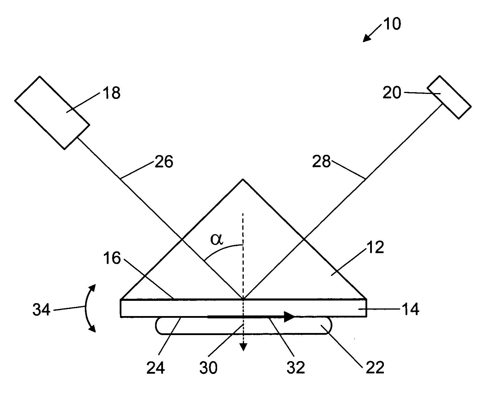
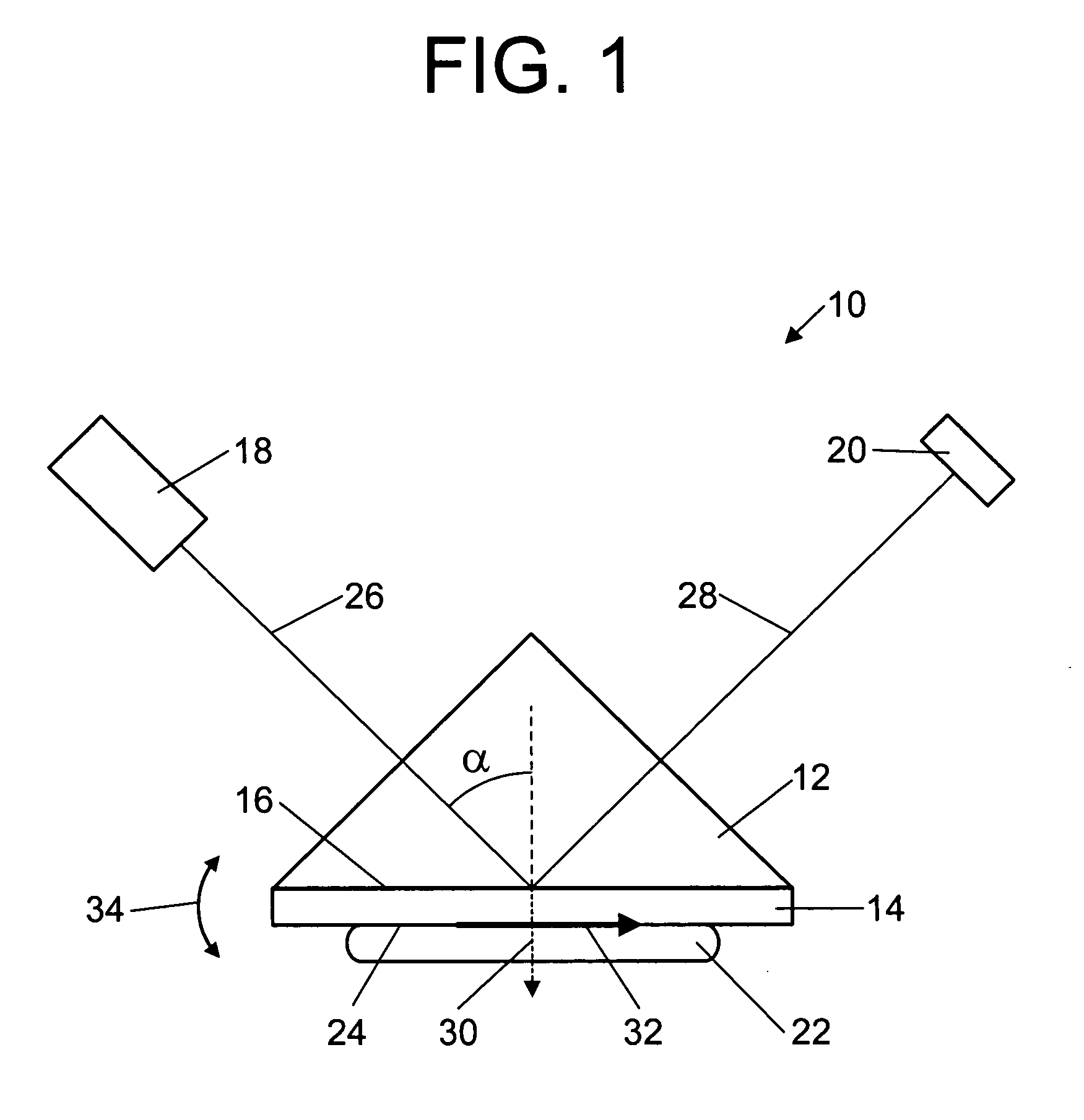
[0016]FIG. 1 shows a surface plasmon resonance biosensor 10 in accordance with the invention which includes a prism 12, a conducting layer 14 contacting one face 16 of the prism 12, a light source 18, and a detector 20. A sample 22 contacts the conducting layer 14 and forms a conducting layer / sample interface 24. The light source 18 emits a collimated monochromatic incident light beam 26 having a wavelength λ0. The light source 18 may be a laser, for example. The incident light beam 26 enters the prism 12 and is incident on the face 16 of the prism 12 contacting the conducting layer 14 at an incident angle α where it is reflected to form a reflected light beam 28 which is detected by the de...


PUM


Abstract

A surface plasmon resonance biosensor uses coupled surface plasmons to decrease the width of a reflectivity dip and thereby increase the sensitivity of the surface plasmon resonance biosensor.

Description

BACKGROUND OF THE INVENTION [0001] Surface plasmon resonance biosensors detect changes in a sample by detecting changes in the index of refraction of the sample, and thus do not require any fluorescent or other labeling of the sample. Accordingly, they are known as label-free biosensors. [0002] In a typical surface plasmon resonance biosensor, a conducting layer is provided between a prism on one side and a sample on the other side. Light of a given wavelength is incident on the conducting layer at an angle through the prism. Almost all of the light will be reflected from the conducting layer except at a specific angle which depends on the index of refraction of the conducting layer and the index of refraction of the sample. At that angle, called the resonance angle, the photons in the incident light are converted to surface plasmons which travel along the interface between the conducting layer and the sample. This causes a sharp dip in the reflectivity of the conducting layer. [000...

Claims


Application Information

Patent Timeline
IPC IPC(8): G01N21/55
CPCG01N21/553
Inventor GRUHLKE, RUSSELL W.
Owner AGILENT TECH INC
Why Eureka
Try Eureka