Image display apparatus and head-mounted display

a display apparatus and display head technology, applied in the field of image display apparatuses, can solve the problems of deterioration of components, drop in image display brightness and deterioration, large and heavy weight, etc., and achieve the effect of avoiding degradation of image quality

Inactive Publication Date: 2007-08-02
KONICA MINOLTA INC
View PDF22 Cites 62 Cited by
  • Summary
  • Abstract
  • Description
  • Claims
  • Application Information

AI Technical Summary

Benefits of technology

[0025]In view of the conventionally encountered inconveniences mentioned above, it is an object of the present invention to provide an image display apparatus and a head-mounted display that are designed to avoid degradation of the quality of the image observed by an observer resulting from the heat generated by a light source.
[0026]To achieve the above object, according to one aspect of the present invention, an image display apparatus is provided with: a light source that emits light having intensity peaks at predetermined wavelengths corresponding to three primary colors; a display element that produces an image by modulating the light emitted from the light source, the display element having color filters corresponding to the three primary colors; an eyepiece optical system that directs image light from the display element to an observer's eye, the eyepiece optical system having a volume-phase-type reflective hologram optical element that diffracts the light from the display element, the hologram optical element having diffraction-efficiency peaks at wavelengths corresponding to the peak-intensity wavelengths of the light emitted from the light source; and a wavelength variation reduction mechanism that reduces variation of the wavelengths of the light emitted from the light source.
[0027]With this construction, variation of the wavelengths of the RGB light emitted from the light source is reduced by the wavelength variation reduction mechanism. Hence, wavelength deviation of the intensity peaks of the light emitted from the light source from the diffraction-efficiency peaks of the hologram optical element can be reduced. Thus, even in a construction employing a high-brightness light source, a display element having RGB color filters, and a volume-phase-type reflective hologram optical element, the light emitted from the light source can be diffracted with the hologram optical element efficiently to present a bright image. Moreover, since variation of the wavelengths of the light emitted from the light source is reduced, the image can be presented with high color purity and high-grade color reproduction.
[0029]With this construction, the heat generated by the light source can be efficiently rejected from the circuit board and efficiently absorbed through the surface of the heat absorbing member. The heat absorbed by the heat absorbing member can then be, via the heat conducting member, led out of the casing so as to be thereby expelled. That is, the heat generated by the light source can be efficiently led out of the casing and thereby expelled. In this way, it is possible to avoid undesirable conditions resulting from the heat generated by the light source, such as a drop in image brightness and deterioration of components.

Problems solved by technology

Inconveniently, as an HMD is used for a long period, the rise in temperature inside its casing resulting from the heat generated by an LED may cause undesirable conditions such as a drop in image display brightness and deterioration of components (for example, a heat-induced deformation in a component).
Providing a head-mounted apparatus with a cooling fan, however, makes it large and heavy, making it difficult for an observer wearing the apparatus on his head to use it for a long period.
When such a high-brightness light source is used, however, the light source itself accumulates heat, and this causes the wavelength of the emitted light to vary.
Thus, if, as a result of a light source accumulating heat, the wavelength of the light emitted from it varies and consequently the peak-intensity wavelength of the light emitted from the light source deviates from the peak-diffraction-efficiency wavelength of the hologram optical element, then the light emitted from the light source cannot be diffracted with the hologram optical element efficiently.
Moreover, a variation in the wavelength of the light emitted from the light source also degrades the color reproduction of the image presented to the observer.

Method used


Image

  • Image display apparatus and head-mounted display
  • Image display apparatus and head-mounted display
  • Image display apparatus and head-mounted display

Examples


embodiment 1

[0071]An embodiment of the present invention will be described below with reference to the accompanying drawings.

1. Construction of an HMD

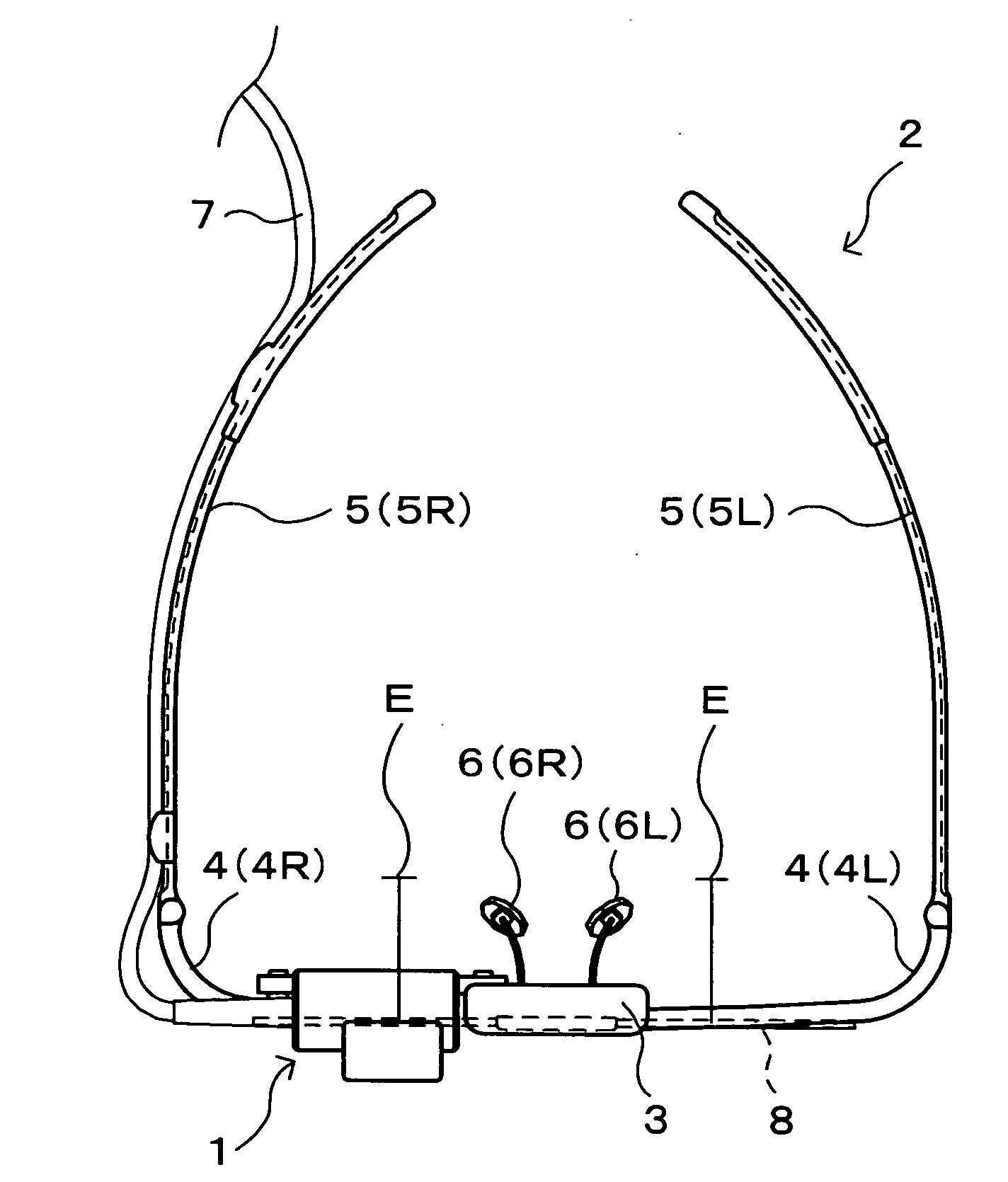
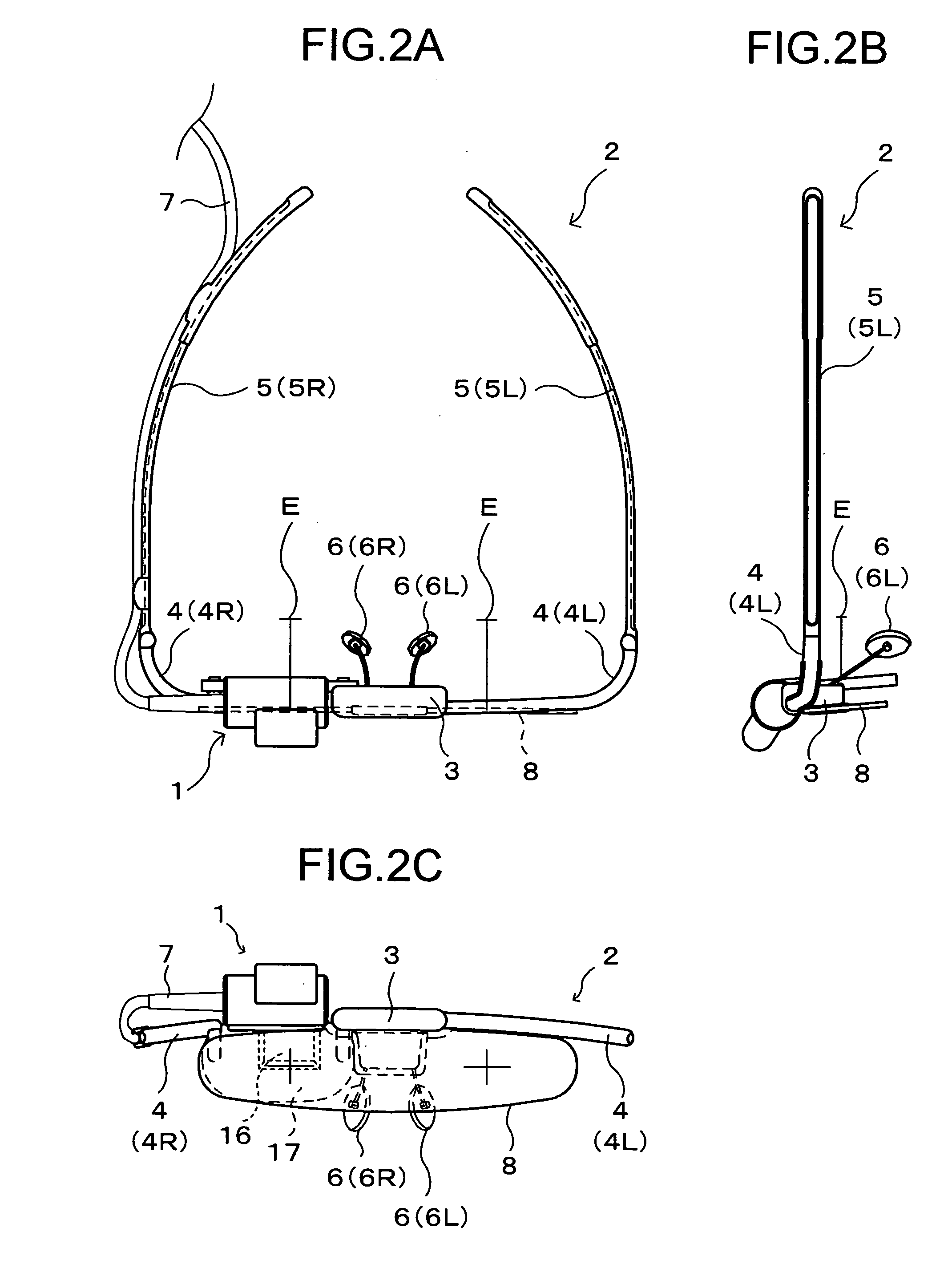
[0072]FIG. 2A is a plan view showing an outline of the construction of a head-mounted display (hereinafter abbreviated to “HMD”) as a first embodiment of the present invention; FIG. 2B is a side view of the HMD; FIG. 2C is a front view of the HMD. The HMD includes an image display apparatus 1 and supporting means 2 (a supporting member) for supporting it. As a whole, the HMD has an exterior appearance like common spectacles having one of the lenses thereof (for example, the left-eye lens) removed.

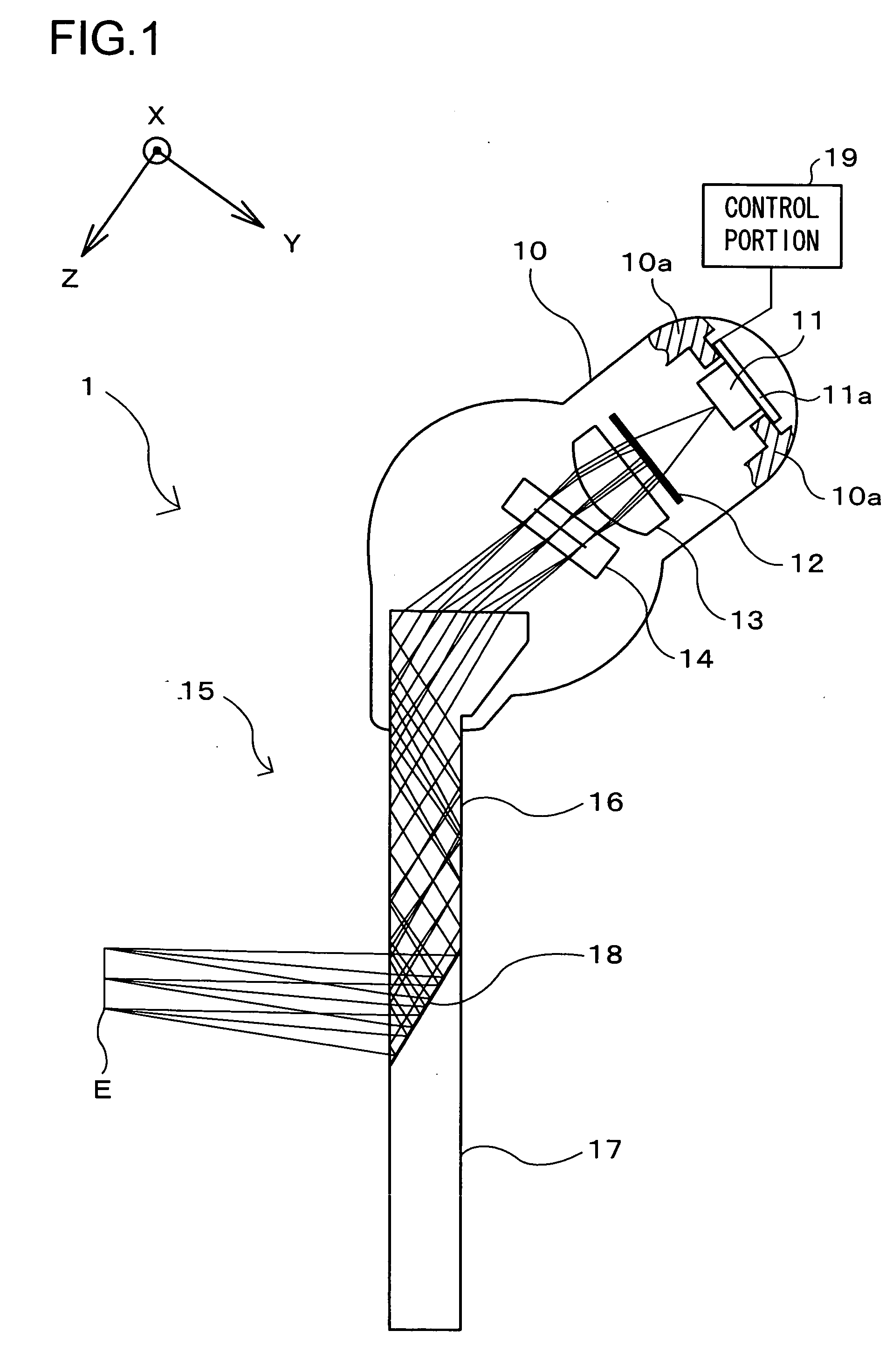
[0073]The image display apparatus 1 allows an observer to observe an outside image in a see-through fashion, and simultaneously displays an image to present a virtual image thereof to the observer. In the image display apparatus 1 shown in FIG. 2C, the portion thereof corresponding to the right-eye lens of spectacles is composed of an eyepiece prism 16 an...

embodiment 2

[0180]Another embodiment of the present invention will be described below with reference to the accompanying drawings. Such components, structures, etc. of Embodiment 2 as are found also in Embodiment 1 will be identified with common reference numerals and symbols, and no explanations thereof will be repeated.

[0181]FIG. 14 is a diagram illustrating the optical paths in the image display apparatus 1 of this embodiment, as optically unfolded in one direction. In this embodiment, the light source 11 is composed of two light source groups 11P and 11Q. In other respects, the construction here is similar to that in Embodiment 1. Thus, the image display apparatus 1 of this embodiment is provided with the wavelength variation reducing means described previously in connection with Embodiment 1.

[0182]FIG. 15 is a plan view of the light source 11 in this embodiment, as seen from the display element 14 side. In the light source 11, the light source group 11P is realized with an integrated RGB L...

embodiment 3

[0201]Still another embodiment of the present invention will be described below with reference to the accompanying drawings. Such components, structures, etc. of Embodiment 3 as are found also in Embodiment 1 or 2 will be identified with common reference numerals and symbols, and no explanations thereof will be repeated.

[0202]FIG. 18 is a cross-sectional view showing an outline of the construction of the image display apparatus 1 of this embodiment, and FIG. 19 is a diagram illustrating the optical paths in the image display apparatus 1, as optically unfolded in one direction. The image display apparatus 1 of this embodiment is constructed similarly to those of Embodiments 1 and 2, the chief differences here being that the eyepiece optical system 15 is replaced with an eyepiece optical system 32 and that the one-way diffuser plate 12 is omitted. Accordingly, the image display apparatus 1 of this embodiment is naturally provided with the wavelength variation reducing means described ...


PUM


Abstract

Variation of the wavelength of the light emitted from a light source is reduced by a wavelength variation reduction mechanism. Hence, wavelength deviation of the intensity peak of the light emitted from the light source from the diffraction-efficiency peak of a hologram optical element is reduced. Thus, even when a high-brightness light source is used, the light emitted therefrom can be diffracted with the hologram optical element efficiently. Moreover, the heat generated by the light source is efficiently rejected through the surface of a land portion of a flexible printed circuit, is then, via an insulating layer of the flexible printed circuit, efficiently absorbed through the surface of a heat absorbing member, and is then, via a shield conductor, led out of a casing, so as to be thereby expelled.

Description

[0001]This application is based on the following Japanese Patent Applications, the contents of which are hereby incorporated by reference:[0002]Japanese Patent Application No. 2006-020065 filed on Jan. 30, 2006;[0003]Japanese Patent Application No. 2006-247520 filed on Sep. 13, 2006; and[0004]Japanese Patent Application No. 2006-310270 filed on Nov. 16, 2006;[0005]Japanese Patent Application No. 2006-310285 filed on Nov. 16, 2006.BACKGROUND OF THE INVENTION[0006]1. Field of the Invention[0007]The present invention relates to an image display apparatus that presents a virtual image of an image displayed on a display element to an observer, and also relates to a head-mounted display (hereinafter also referred to as “HMD”) that is provided with such an image display apparatus.[0008]2. Description of Related Art[0009]There have conventionally been proposed various image display apparatuses that allow observation of a virtual image of an image displayed on a display element such as a liq...

Claims


Application Information

Patent Timeline
Patent Type & Authority Applications(United States)
IPC IPC(8): G03H1/00
CPCG02B5/32G02B27/017G02B27/0172G02B2027/0116G03H2222/20G02B2027/0178G03H1/02G03H2001/0212G02B2027/0174
Inventor TANIJIRI, YASUSHIKASAI, ICHIRONODA, TETSUYAYAMAGUCHI, HIROSHISHIMIZU, YOSHIE
Owner KONICA MINOLTA INC
Why Eureka
Try Eureka