

Serrated kneading disk and kneading block
- Summary
- Abstract
- Description
- Claims
- Application Information
AI Technical Summary
Benefits of technology
Problems solved by technology
Method used
Image

Examples
first embodiment
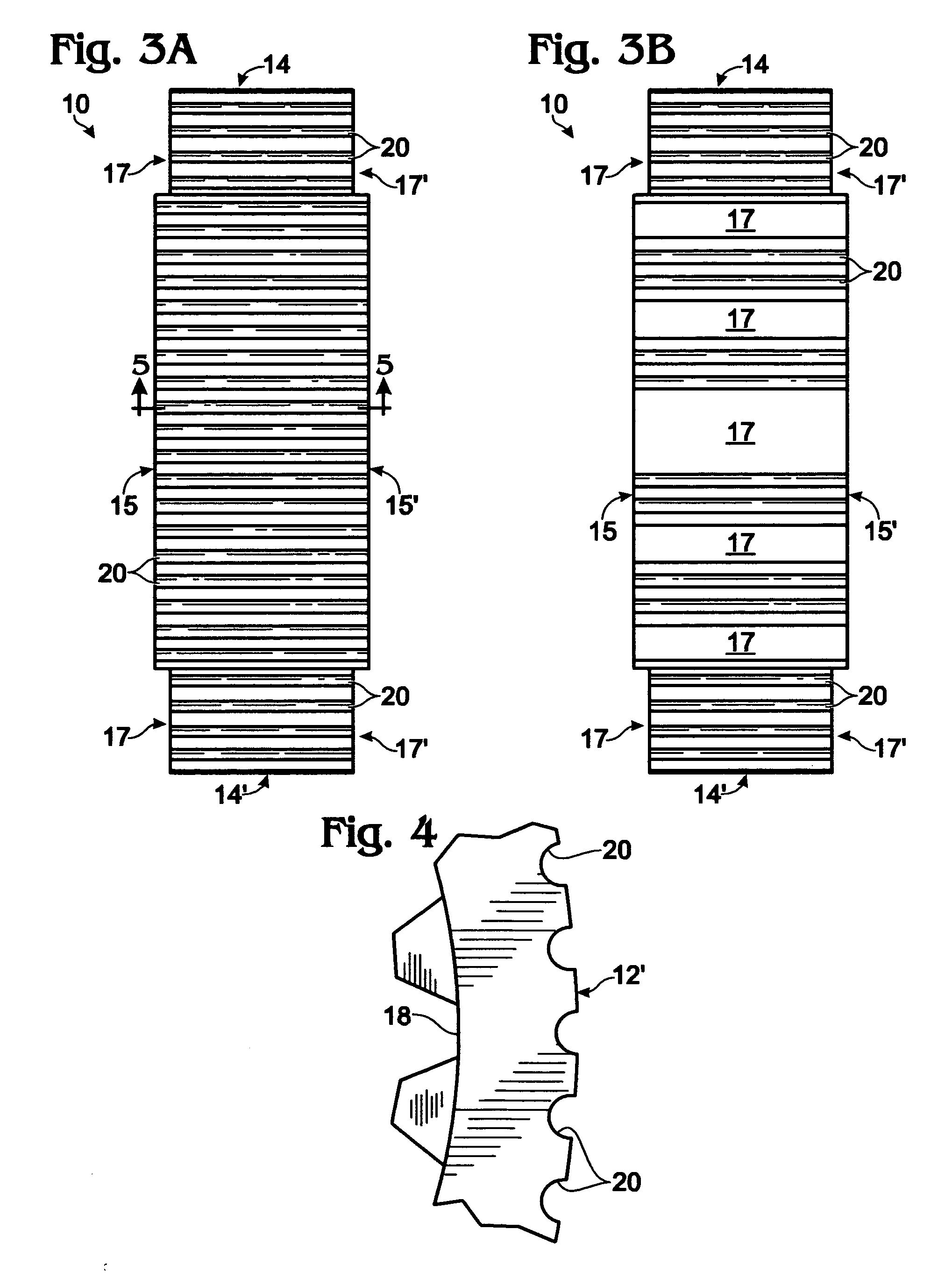
[0031]FIG. 5A shows groove 20 taken along line 5-5 of FIG. 3. Groove 20 has a bottom 22 which slopes upwardly from face 15 to face 15′, going from a deep portion adjacent face 15 to a shallow portion adjacent face 15′.
embodiment 120
[0032]FIG. 5B shows a second groove embodiment 120. Groove 120 has a bottom 122 which slopes downwardly from face 15 to face 15′, going from a shallow portion adjacent face 15 to a deep portion adjacent face 15′.
embodiment 220
[0033]FIG. 5C shows a third groove embodiment 220. Groove 220 has a bottom 222 which slopes upwardly from face 15 to a mid-portion between face 15 and face 15′, and slopes downwardly from a mid-portion between face 15 and face 15′ to face 15′. Thus, groove 222 goes from a deep portion adjacent face 15 to a shallow portion adjacent the mid-portion between face 15 and face 15′, and goes from a shallow portion adjacent the mid-portion between face 15 and face 15′ to a deep portion adjacent face 15′.
PUM
| Property | Measurement | Unit |
|---|---|---|
| Angle | aaaaa | aaaaa |
| Radius | aaaaa | aaaaa |
| Depth | aaaaa | aaaaa |
Abstract
Description
Claims
Application Information