Image forming apparatus

a technology of forming apparatus and forming tube, which is applied in the direction of electrographic process apparatus, instruments, optics, etc., can solve the problems of inability to reduce frictional load, inability to ensure the necessary properties of toner, and inability to achieve the effect of reducing frictional load

Active Publication Date: 2007-08-02
CANON KK
View PDF7 Cites 4 Cited by
  • Summary
  • Abstract
  • Description
  • Claims
  • Application Information

AI Technical Summary

Benefits of technology

[0019] An object of the present invention is to provide an image forming apparatus capable of obtaining a uniform coated state of a developer on a developer carrying member.

Problems solved by technology

Also such agglomeration may result in density unevenness in an image and a toner dripping (an agglomerated toner block dripping onto an image in spot-like manner).
However, the former method involves a basic construction such as a triboelectric charging by the developing blade or a contact with the developing drum, so that the extent of reduction in the frictional load has to be limited.
Also the latter method is inevitably limited in consideration of assuring necessary properties for the toner, such as fluidity, triboelectric chargeability and fixing property.
H09-127771 between the developing roller and the developing blade may be unable to avoid the toner dripping or the density unevenness with a toner in a state with changed physical properties after repeated image forming operations.

Method used


Image

  • Image forming apparatus
  • Image forming apparatus
  • Image forming apparatus

Examples


Embodiment Construction

[0028] In the following, there will be explained, in detail, preferred embodiments for executing the present invention, with reference to drawings and examples. However, in the examples, dimensions, materials, shapes, relative positions and the like of constituent components are not to be construed to restrict the present invention to such description, unless particularly specified otherwise. Also a material, a shape and the like of a member, once explained in the description, are assumed to be similar throughout the text, unless specifically described otherwise again.

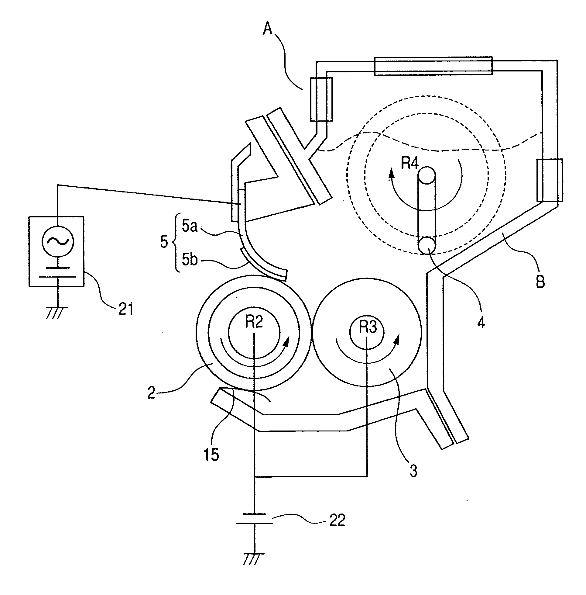
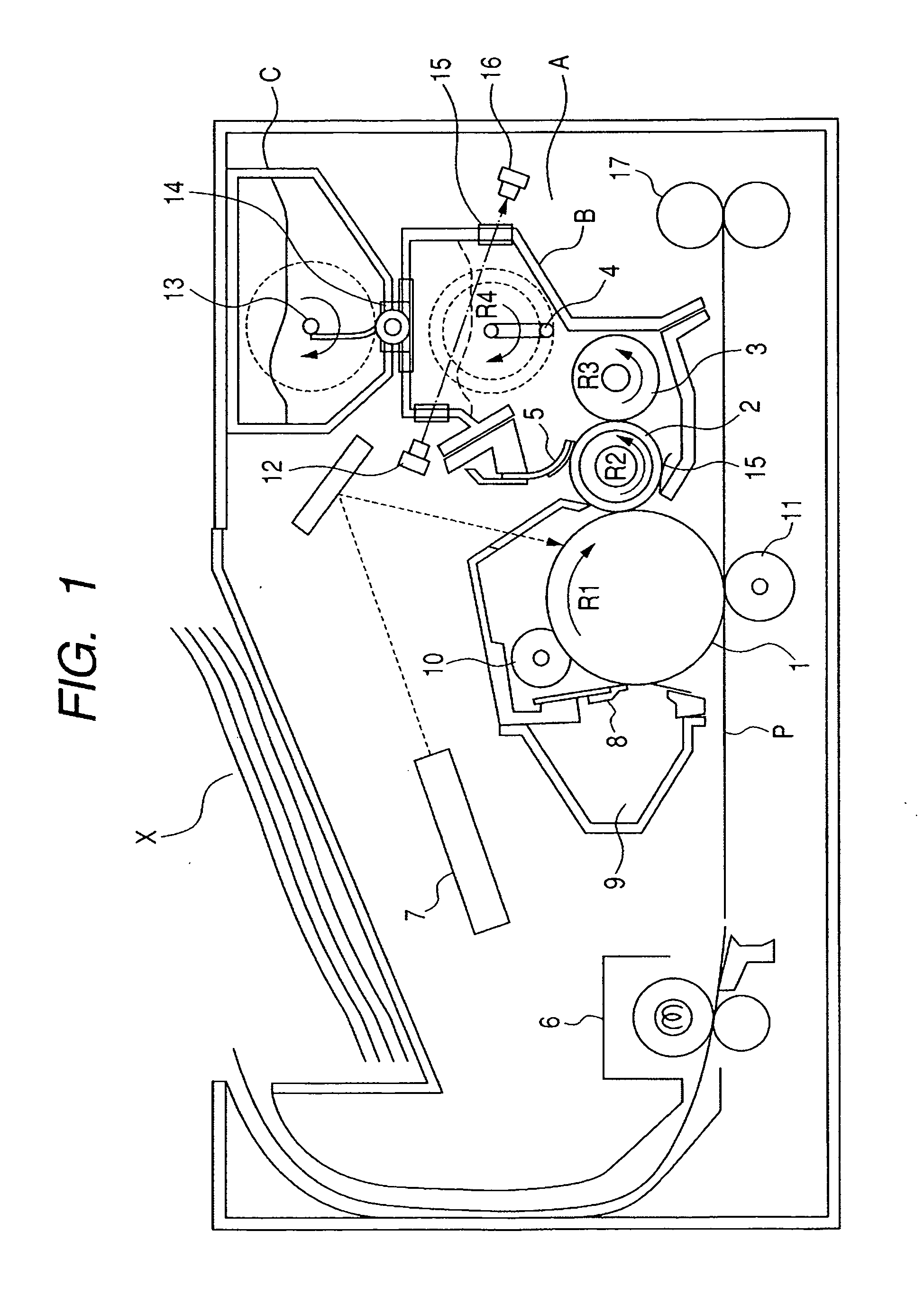
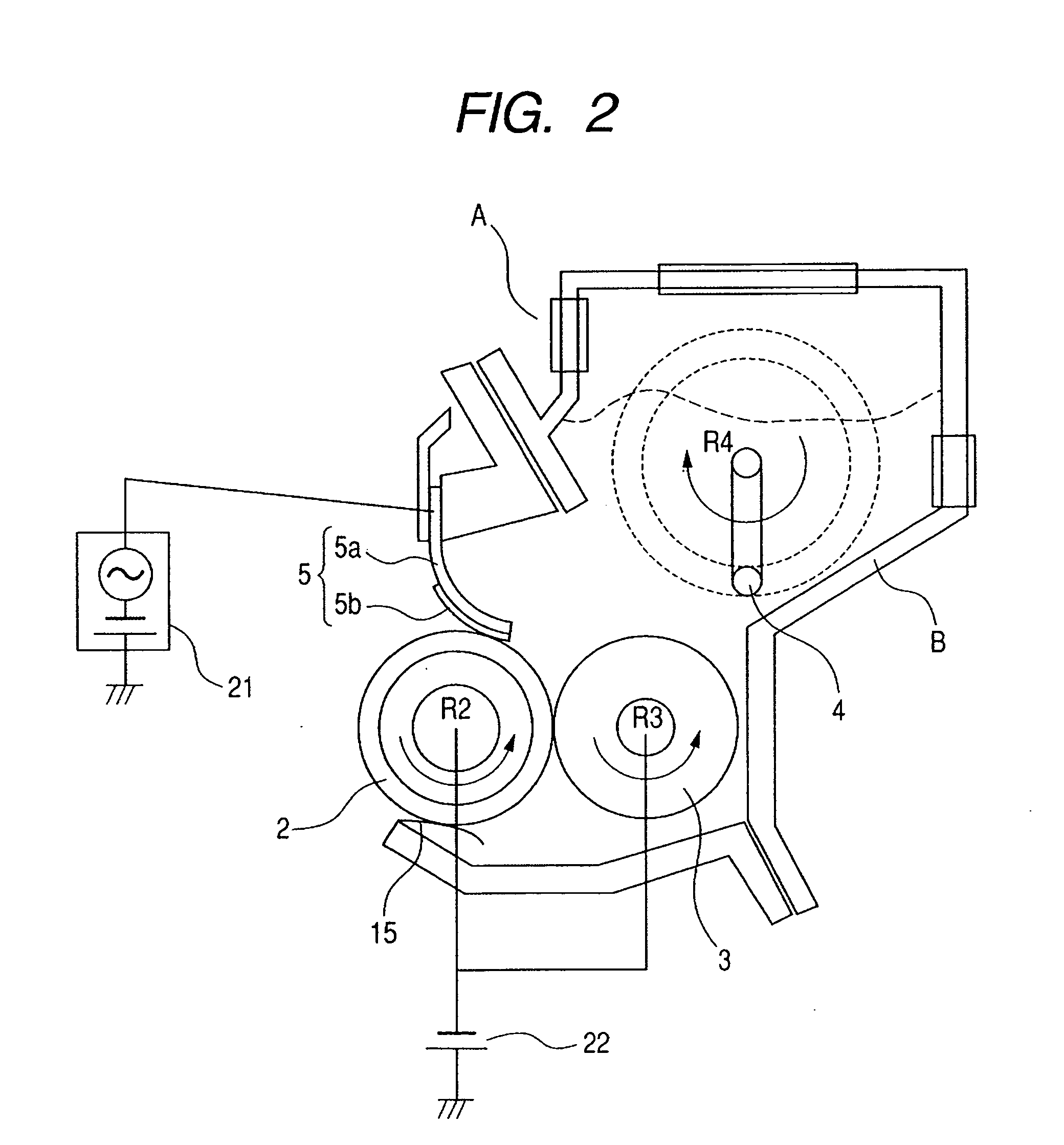
[0029]FIG. 1 is a schematic cross-sectional view showing an image forming apparatus embodying the present invention. The present embodiment explains a monochromatic image forming apparatus for forming an image of black color only, but the present invention is not limited to such embodiment and is likewise applicable to a color image forming apparatus-for an image formation of plural colors. Also a member having an equ...


PUM


Abstract

The invention realizes a uniform toner coating on a developing roller, thereby preventing a density unevenness and a toner dripping and suppressing a developing roller set mark image in a contact developing method, by conditions that the DC voltage applied to the developer regulating member is the same as the DC voltage applied to the developer carrying member or at a side of a charging polarity of the developer with respect to the DC voltage applied to the developer carrying member; and a frequency f (Hz) and a peak electric field strength E (V/m) of the AC electric field formed by the AC voltage between the developer regulating member and the developer carrying member, and a peripheral speed v (m/s) of the image bearing member satisfies conditions:
4.2×v≦f≦2500 and
2.2×10⁶≦E≦5.2×10⁶.

Description

BACKGROUND OF THE INVENTION [0001] 1. Field of the Invention [0002] The present invention relates to an image forming apparatus for visualizing an electrostatic image, formed on an image bearing member for example by an electrostatic recording method, with a developer thereby obtaining a visible image. The image forming apparatus includes, for example, a copying machine, a printer (such as an LED printer or a laser beam printer), a facsimile apparatus, and a work processor. [0003] 2. Related Background Art [0004] In an image forming apparatus of an electrophotographic method, an image bearing member such as an electrophotographic photosensitive member is charged and then exposed to light according to image information, whereby an electrostatic image is formed. Such electrostatic image is formed, by the supply of a developer to the image bearing member by developing means, into a developer image. Then such developer image is transferred by transfer means such as a transfer charger on...

Claims


Application Information

Patent Timeline
Patent Type & Authority Applications(United States)
IPC IPC(8): G03G15/08
CPCG03G15/0812
Inventor HASHIMOTO, KAZUNORIKANAZAWA, TAKAYUKI
Owner CANON KK
Why Eureka
Try Eureka