
Physiological alarm notification system

a physiological alarm and notification system technology, applied in the field of physiological alarm notification system, can solve the problems of using proprietary networks for alarm notification, not adequately addressing the workflow model of hospital general care floors, and assuming the cost of such components

Inactive Publication Date: 2007-08-02
JPMORGAN CHASE BANK NA
View PDF110 Cites 389 Cited by
  • Summary
  • Abstract
  • Description
  • Claims
  • Application Information

AI Technical Summary

Problems solved by technology

However, this conventional central station paradigm does not adequately address the workflow models in hospital general care floors where nurse to patient ratios are often 1:6 or greater, where nurses have a lower skill set than ICUs, and where patients are often housed in private or semi-private rooms not in direct view of clinicians.
Some systems are adapted to include clinician paging to enable secondary alarm notification to mobile health care personnel, but such systems still rely on a central station concept and therefore bear the cost for such components.
There are also drawbacks to using proprietary networks for alarm notification.
One drawback is that proprietary networks tend to be costly to obtain, setup, and maintain.
Another drawback is that proprietary networks may provide only limited amounts of data to remote devices due to physical limitations in legacy hardware and software.
Consequently, replacing or upgrading these patient monitoring devices simultaneously requires replacement of the communications hardware, which is cost-inefficient.
However, these docking stations are often wired into a proprietary network and suffer the drawbacks attendant to such networks.

Method used


Image

  • Physiological alarm notification system
  • Physiological alarm notification system
  • Physiological alarm notification system

Examples


Embodiment Construction

[0028] Various embodiments according to the invention will be described hereinafter with reference to the accompanying drawings. These embodiments are illustrated and described by example only, and are not intended to limit the scope of the invention.

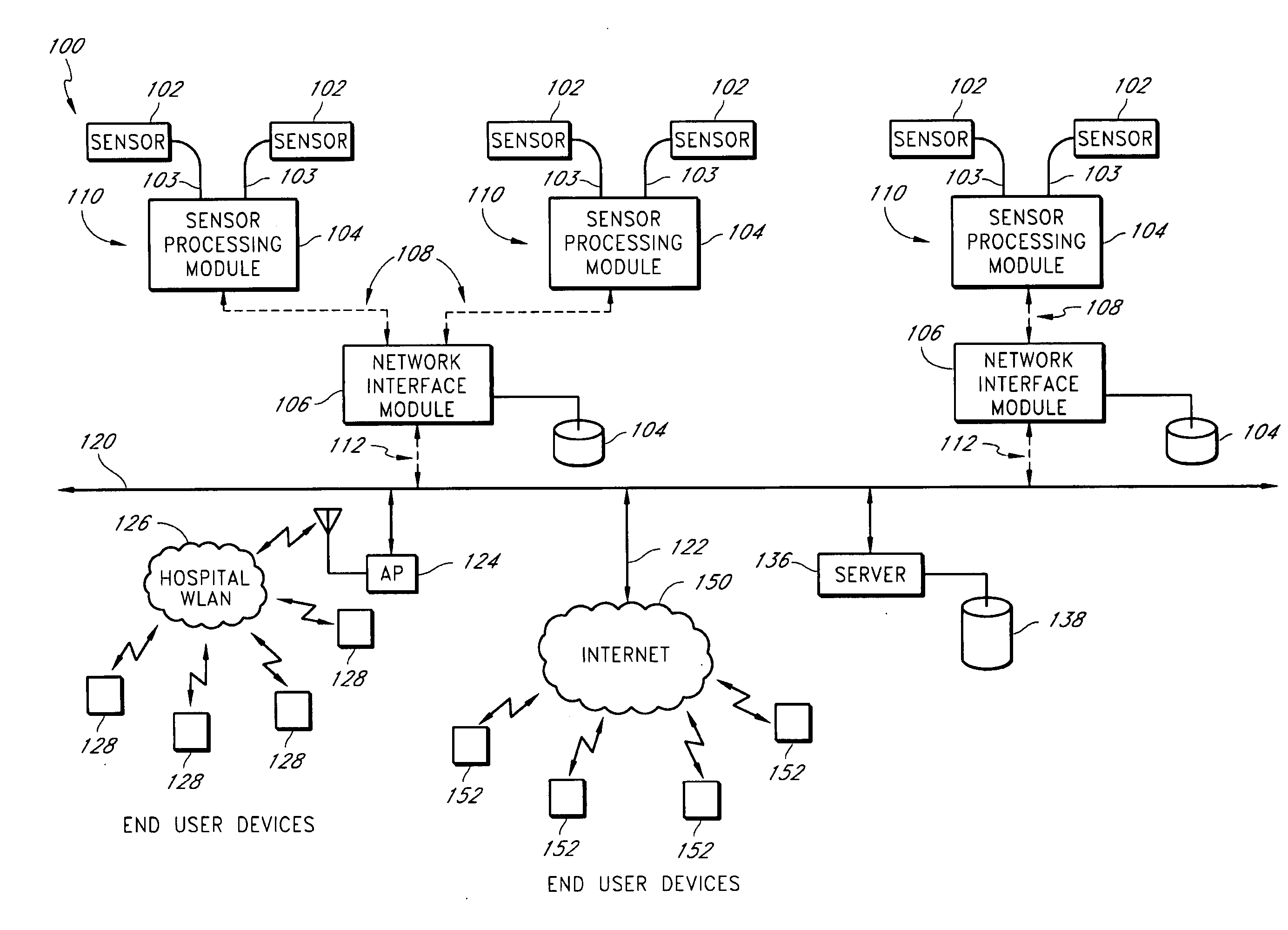
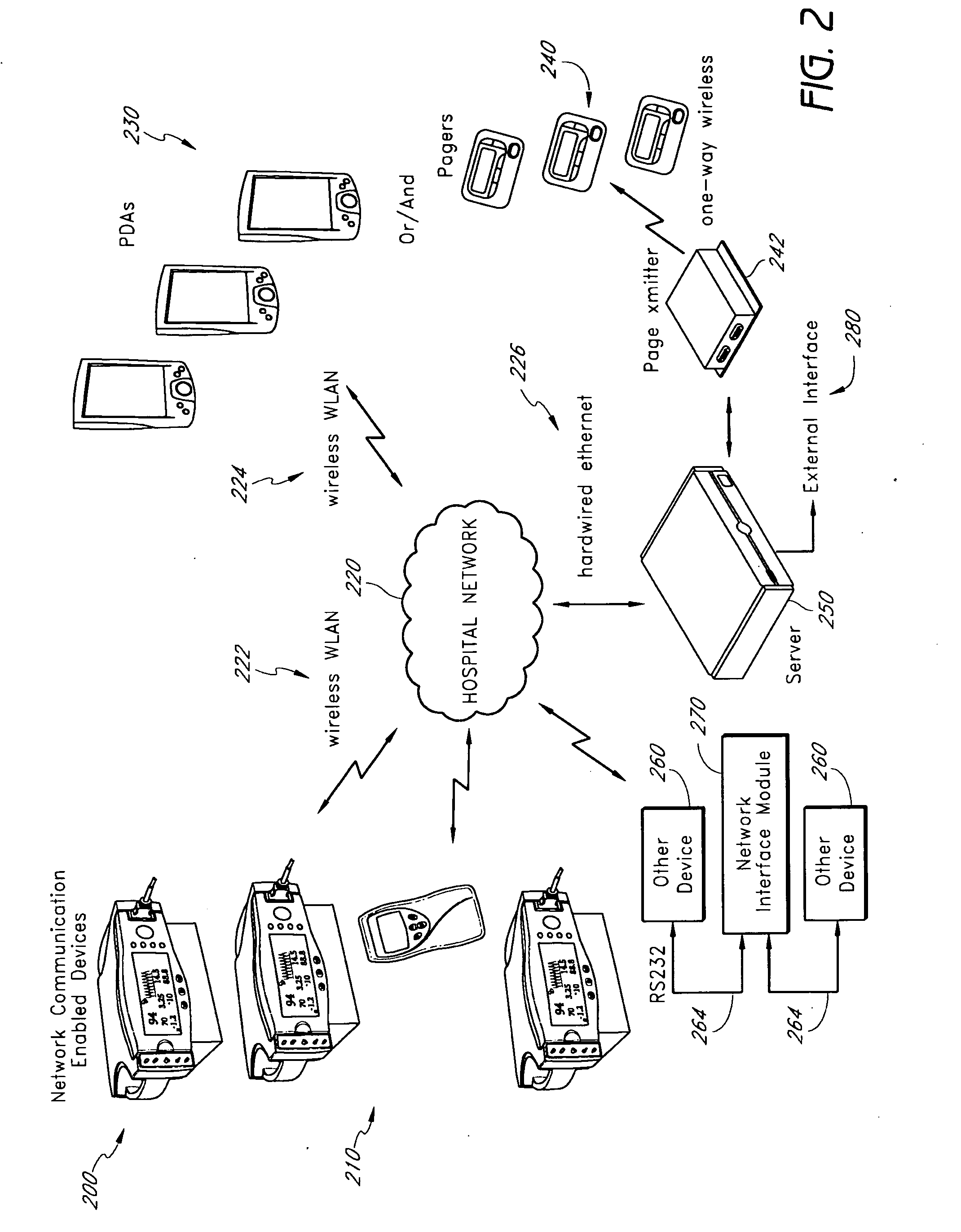
[0029] In various embodiments, physiological monitoring systems are systems that monitor physiological signals generated by a medical patient and process the signals to determine any of a variety of physiological parameters of the patient. For example, in some cases, a physiological monitoring system can determine any of a variety of physiological parameters of a patient, including respiratory rate, inspiratory time, expiratory time, i:e ratio (e.g., inspiration-to-expiration ratio), inspiratory flow, expiratory flow, tidal volume, minute volume, apnea duration, breath sounds, rales, rhonchi, stridor, and changes in breath sounds such as decreased volume or change in airflow. In addition, in some cases the physiological monitoring syst...


PUM


Abstract

A method of context-based communication of physiological information over a network includes receiving physiological information, preparing a contextual data package, establishing a network connection, and communicating the contextual data package. The physiological information is received with a portable network interface module from at least one physiological monitor coupled to a single medical patient. The physiological information is related to a physiological condition of the medical patient, and the portable network interface module is exclusively assigned to the medical patient. The contextual data package is prepared with the portable network interface module. The contextual data package includes context information related to the medical patient and the physiological information. The network connection is established with a user over a network with the portable network interface module, and the portable network interface module manages the network connection with the user. The contextual data package is communicated to the user over the network with the network connection.

Description

CROSS-REFERENCE TO RELATED APPLICATIONS [0001] This application claims priority from U.S. Provisional Application No. 60 / 741,835 filed Dec. 3, 2005, entitled “Physiologic Alarm Notification System,” which is incorporated herein by reference. This application also claims priority from U.S. Provisional Application No. 60 / 756,241 filed Jan. 3, 2006, entitled “Physiologic Alarm Notification System,” which is also incorporated herein by reference.BACKGROUND [0002] 1. Field of the Invention [0003] This invention relates to a system, apparatus, and method for transmitting physiological information over a network. In certain embodiments, the invention relates to transmitting physiological information and patient context information to an end user over a shared network using a network interface module. [0004] 2. Description of the Related Art [0005] Hospitals, nursing homes, and other patient care facilities typically include patient monitoring devices at one or more bedsides in the facility...

Claims


Application Information

Patent Timeline
Patent Type & Authority Applications(United States)
IPC IPC(8): G06F15/173G06F15/16A61B5/00G16H40/67
CPCA61B5/024A61B5/0402A61B5/0816A61B5/145G06F19/322G06F19/327A61B5/0022G06F19/345G06F19/3487G08B21/0453H04L67/12A61B5/002G06F19/3418G16H10/60G16H40/20G16H50/20G16H15/00G16H40/67A61B5/318
Inventor WELCH, JAMES P.SAMPATH, ANANDSHIHABI, MAZEN
Owner JPMORGAN CHASE BANK NA
Learn More