Hard Drive with Metal Casing and Ground Pin Standoff to Reduce ESD Damage to Stacked PCBA's

a hard drive and metal casing technology, applied in the field of flashmemory hard drives, can solve the problems of more prone to damage of solid-state devices

Inactive Publication Date: 2007-08-02
SUPER TALENT ELECTRONICS
View PDF4 Cites 28 Cited by
  • Summary
  • Abstract
  • Description
  • Claims
  • Application Information

AI Technical Summary

Problems solved by technology

However, these solid-state devices may be more prone to damage from tiny electrical shocks or electro-static-discharge (ESD).

Method used


Image

  • Hard Drive with Metal Casing and Ground Pin Standoff to Reduce ESD Damage to Stacked PCBA's
  • Hard Drive with Metal Casing and Ground Pin Standoff to Reduce ESD Damage to Stacked PCBA's
  • Hard Drive with Metal Casing and Ground Pin Standoff to Reduce ESD Damage to Stacked PCBA's

Examples


case 20

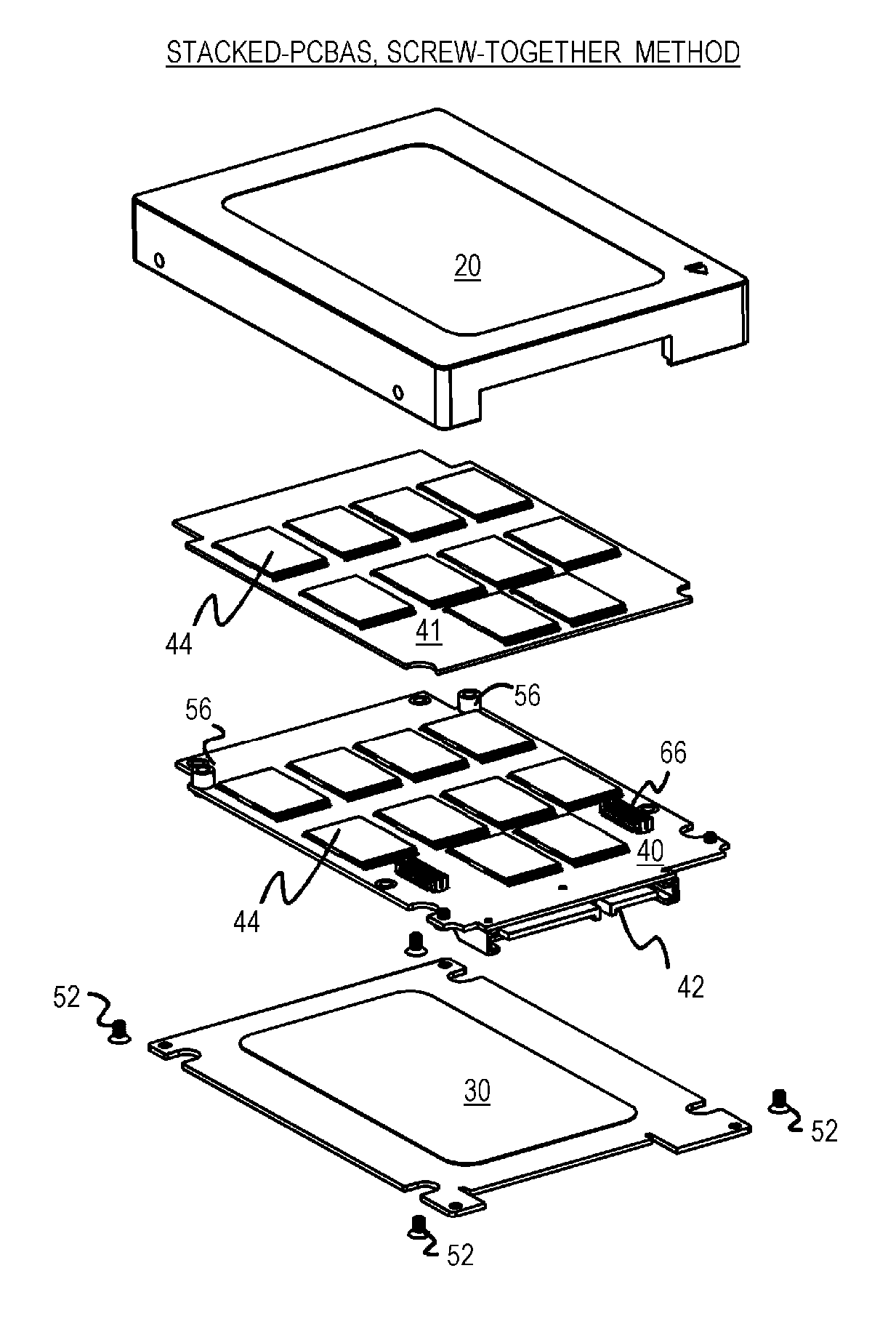
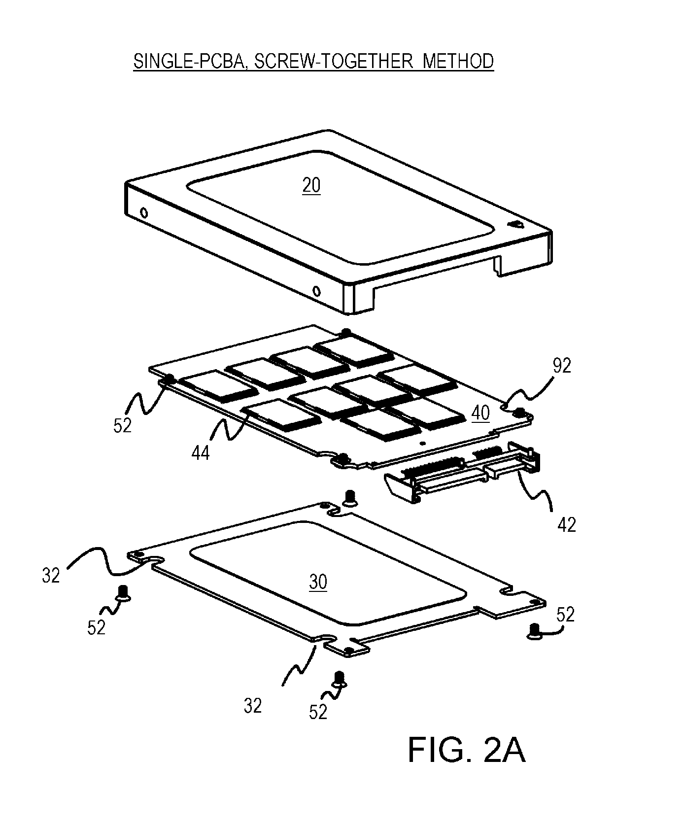
[0030] Upper case 20 and lower case 30 are formed of metal, such as by molding, stamping, or other processes. Four screws 52 fit into four corner holes in lower case 30 and then into the case-grounding tabs formed at the corners of upper case 20 on the four primary axes.

[0031] Four cutouts 32 in lower case 30 near the corners fit around alignment tabs that are also formed in upper case 20. Notches 92 in PCBA 40 also fit around these alignment tabs. Before screwing cases 20, 30 together, PCBA is fitted into upper case 20 and fits against alignment tabs and on metal standoff pedestals formed inside upper case 20. The metal standoff pedestals are on the secondary axes.

[0032] The secondary axis is aligned with the screw holes of PCBA 40 after PCBA 40 is fitted inside upper case 20, and the case-grounding tab along the primary axis of the triple-axis case-grounding tabs is formed inside upper case 30.

[0033] Four screws 52 are fitted into screw holes in PCBA 40 and then into metal stand...


PUM


Abstract

A case-grounded flash-memory drive has a printed-circuit board assembly (PCBA) with flash-memory chips and a controller chip. The PCBA is encased inside an upper case and a lower case, with a Serial AT-Attachment (SATA) connector that fits through an opening between the cases. The cases can be assembled with the PCBA by a screw-together or thermal-bond adhesive method. Triple-axis case-grounding tabs draw any electro-static-discharges (ESD) current off the upper case along a primary axis and onto a PCBA ground through a secondary axis that is screwed into the PCBA. An intermediary axis between the primary and secondary axes fits around a PCBA notch while the secondary axis passes through a metalized alignment hole on the PCBA for grounding. When the SATA connector is inserted into a host, the host ground sinks ESD currents collected by the triple-axis case-grounding tabs.

Description

RELATED APPLICATION [0001] This application is a continuation-in-part (CIP) of the co-pending applications for “Thin Hard Drive with 2-Piece Casing and Ground Pin Standoff to reduce ESD Damage to Stacked PCBA's”, U.S. Ser. No. 11 / 683,292, filed Mar. 7, 2007, “Thin Flash-Hard-Drive with Two-Piece Casing”, U.S. Ser. No. 11 / 309,843, filed Oct. 11, 2006, “Light-Weight Flash Hard Drive With Plastic Frame”, U.S. Ser. No. 10 / 990,887, filed Nov. 16, 2004, and “Electronic Data Storage Medium with Fingerprint Verification Capability”, U.S. Ser. No. 09 / 478,720, filed Jan. 6, 2000. This patent is also related to “Stacking Memory Chips using Flat Lead-Frame with Breakaway Insertion Pins and Pin-to-Pin Bridges”, U.S. Pat. No. 6,933,209, dated Aug. 23, 2005.FIELD OF THE INVENTION [0002] This invention relates to flash-memory hard drives, and more particularly to manufacturing a flash drive with a two-piece metal casing, grounded standoff, and dual printed-circuit boards (PCBs). BACKGROUND OF THE I...

Claims


Application Information

Patent Timeline
Patent Type & Authority Applications(United States)
IPC IPC(8): H04L9/00H05K5/02G11C11/34H05K5/00
CPCH05K5/0269
Inventor NI, JIM CHIN-NANLI, KEN QI-JINMA, ABRAHAM C.SHEN, MING-SHIANG
Owner SUPER TALENT ELECTRONICS
Why Eureka
Try Eureka