Method and apparatus for refueling multiple vehicles

a technology for refueling multiple vehicles and vehicles, applied in the direction of transportation items, liquid handling, packaging goods types, etc., can solve the problems of time-consuming and expensive processes

Inactive Publication Date: 2007-08-09
RYAN CENT
View PDF10 Cites 152 Cited by
  • Summary
  • Abstract
  • Description
  • Claims
  • Application Information

AI Technical Summary

Benefits of technology

[0008] In many cases, the refueling dock should be located in this staging area. When refueling is required or when the equipment is not in use, it can be parked within range of the hoses on the refueling dock. Fuel may then be pumped through the manifold of the refueling e pieces of equip

Problems solved by technology

This is a time consumi

Method used


Image

  • Method and apparatus for refueling multiple vehicles
  • Method and apparatus for refueling multiple vehicles
  • Method and apparatus for refueling multiple vehicles

Examples


Embodiment Construction

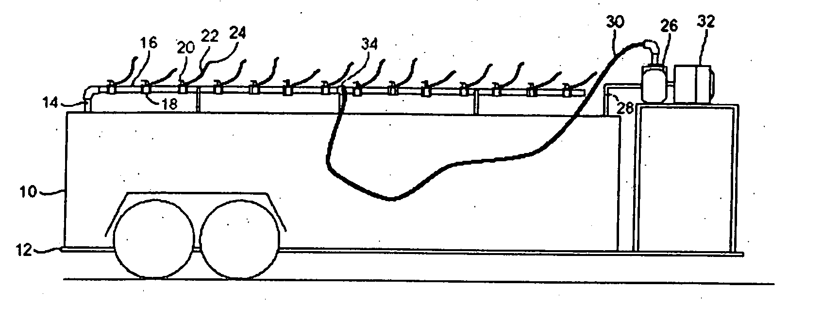
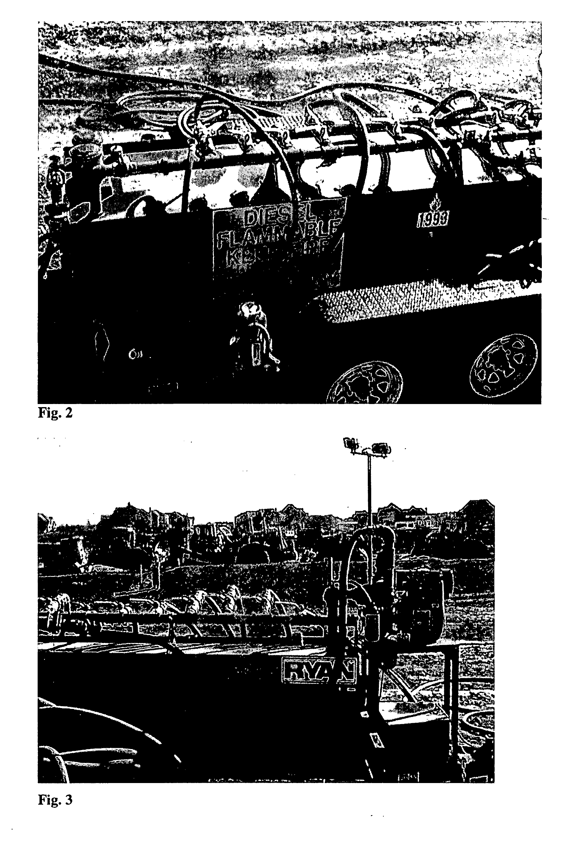
[0014]FIG. 1 illustrates one example of a refueling dock 5 that uses the present invention. In general, the refueling dock includes a fuel tank 10, wheeled base 12, a fuel tank outlet line 14, and a manifold 16. These components will be described in more detail below. The base may also have an enclosed housing for the tank.

[0015] The illustrated fuel tank 10 is supported by the wheeled base 12, and is connected to the manifold 16 through the fuel tank outlet line 14. The fuel tank may be fitted with bung holes that can be used to attach pipes. As explained below, the fuel tank outlet line can be used to convey fuel from the tank to the manifold.

[0016] The illustrated manifold 16 is located above and outside the fuel tank 10. It is constructed of metal pipe and contains a plurality of outlet openings 18. Each outlet opening may include a valve, which, in this illustration, is a ball valve 20. A plurality of refueling hoses 22 extend from the outlet openings to refueling nozzles 24....


PUM

PropertyMeasurementUnit
Timeaaaaaaaaaa
Flow rateaaaaaaaaaa
Widthaaaaaaaaaa

Abstract

A refueling dock for refueling multiple vehicles at one time is disclosed. The dock has a manifold that has an inlet that can be connected to a fuel tanker truck and a plurality of outlet openings. Each outlet opening has a valve that controls the flow of fuel through the hose. A nozzle is fitted to the hose and is located at the end of the hose distant from the outlet opening. Two or more hoses can be simultaneously connected to different equipment in need of refueling. A valved fuel tank inlet line enables fuel to flow from the manifold to a fuel tank on the dock. When needed, fuel from the tank can then be pumped to the manifold through a fuel tank outlet line,.which can be connected to the same inlet on the manifold that is used to receive fuel from the tanker trick.

Description

RELATED APPLICATION [0001] This application claims priority to U.S. Provisional application No. 60 / 743,209, filed Feb. 1, 2006, which is incorporated by reference in its entirety.FIELD OF THE INVENTION [0002] This invention is directed to a method and apparatus for refueling vehicles used on a construction site and, in particular, to a method and apparatus for refueling multiple vehicles at one time using a refueling dock with multiple fuel hoses. BACKGROUND OF THE INVENTION [0003] While working on a construction site, large vehicles that are used in moving and hauling dirt and debris need to be refueled. To deal with this problem, construction companies generally hire fuel companies to bring a large fuel tanker truck to the construction site and connect the tanker truck individually to each piece of equipment that needs to be refueled. This is a time consuming, expensive process. The tanker truck travels to the location of each piece of equipment and refuels one piece of equipment ...

Claims


Application Information

Patent Timeline
IPC IPC(8): B65B1/04
CPCB60S5/02B60P3/14
Inventor FELL, JOE
Owner RYAN CENT
Why Eureka
Try Eureka