Welding wire feed speed control system method

Active Publication Date: 2007-08-09
ILLINOIS TOOL WORKS INC
View PDF6 Cites 45 Cited by
  • Summary
  • Abstract
  • Description
  • Claims
  • Application Information

AI Technical Summary

Problems solved by technology

Unfortunately, in many cases, the weld operator is a novice to field, especially in the case of portable welding devices.
If the operator does not properly adjust the voltage and wire-feed speed settings, the arcing may not be sufficient to produce a good

Method used


Image

  • Welding wire feed speed control system method
  • Welding wire feed speed control system method
  • Welding wire feed speed control system method

Examples


Example

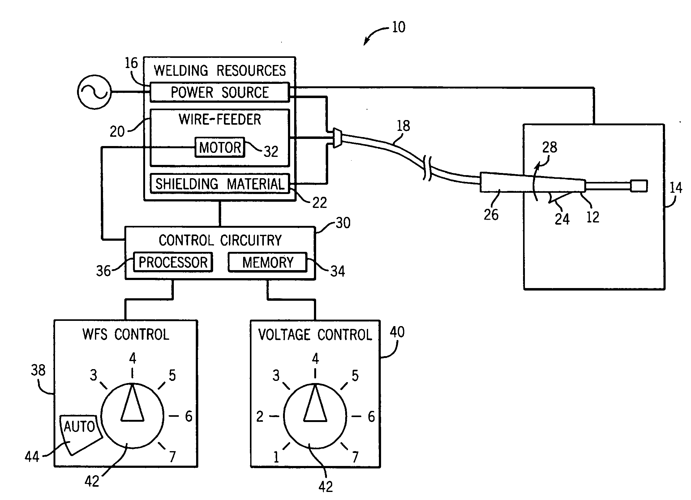
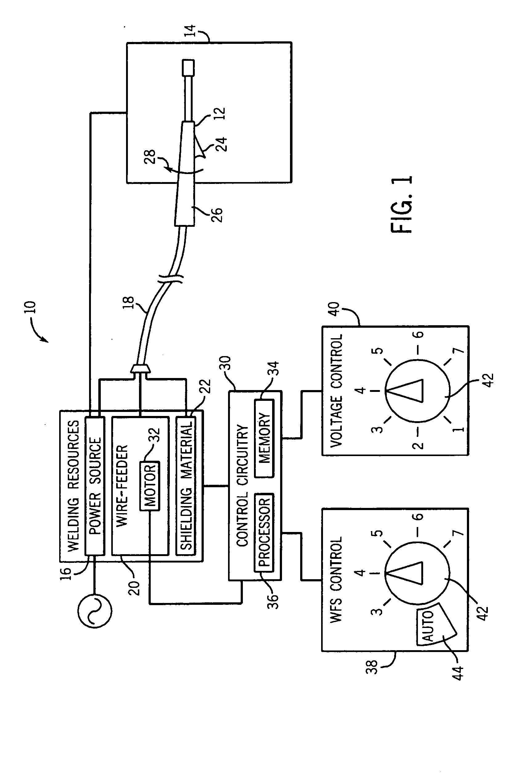
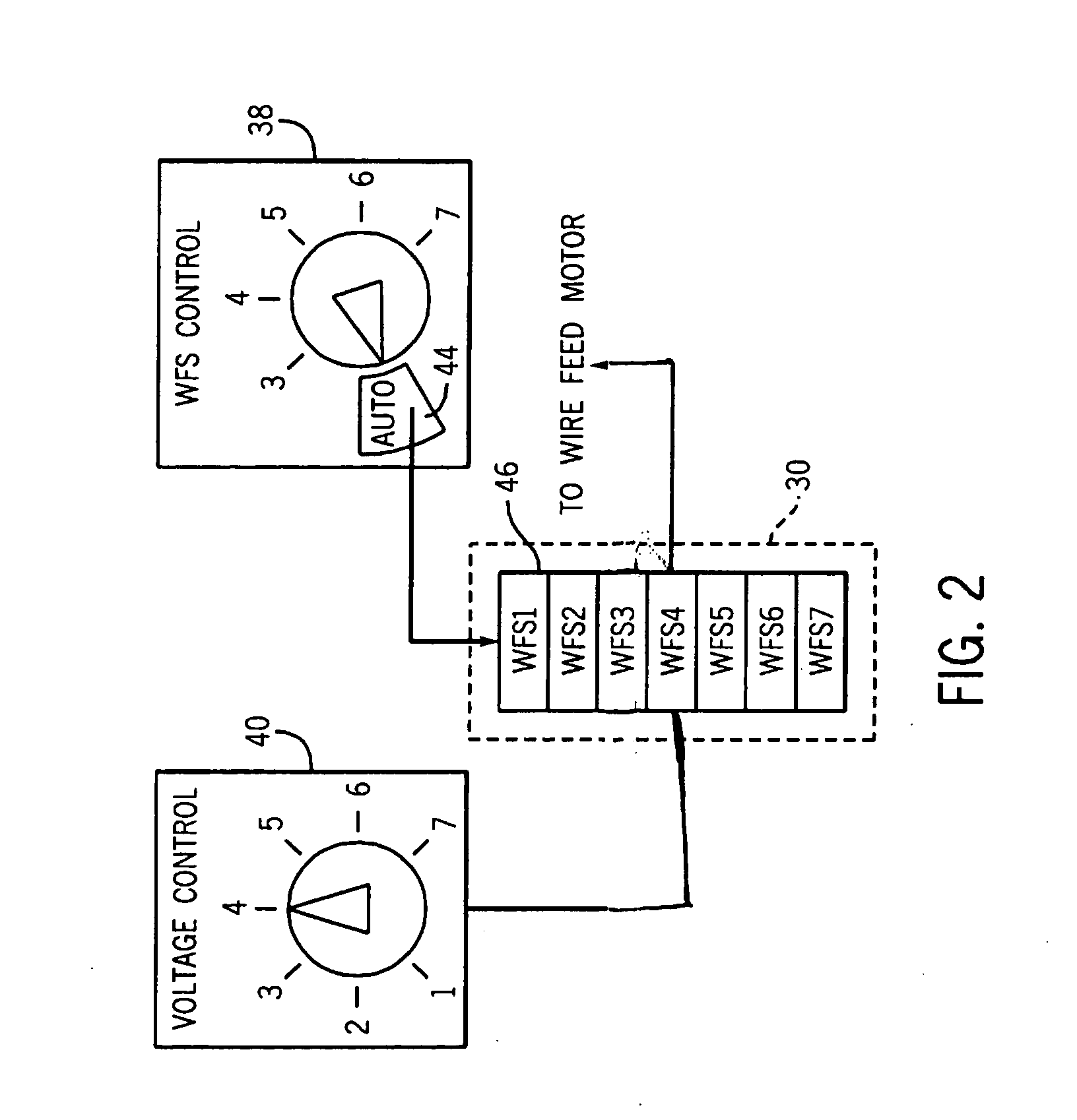
[0012] As discussed in detail below, the present technique, in accordance with certain embodiments, provides method and apparatus for controlling the advancement of wire electrode in a welding device. For example, a metal-inert-gas (MIG) welding system incorporating the present technique can include an “AUTO” setting that links the wire-feed speed to the voltage-level or vice-versa. Thus, in such a system, if an operator were to adjust the voltage to the wire electrode, the wire-feed speed would be automatically adjusted to accommodate the new voltage setting. Alternatively, the selected wire-feed speed can automatically determine an output voltage level. Advantageously, the linked relationship between the voltage-level control and the wire-feed control can assist an operator in obtaining desirable performance and, furthermore, can facilitate multifunctional control of the welding device via a single input knob. FIG. 1 illustrates an exemplary welding system that includes an embodim...


PUM

PropertyMeasurementUnit
Electric potential / voltageaaaaaaaaaa
Poweraaaaaaaaaa

Abstract

A welding system is disclosed in which the rate of advancement of wire electrode is determined automatically. The device can include a control circuit that determines the rate of advancement of the wire electrode in response to a signal from the voltage selection device of the welding system. Depending upon the operator selected voltage which is selected via the voltage selection device, the control circuit will determine the appropriate rate of wire electrode advancement and control the advancement mechanism (e.g., electric motor) accordingly. Linking of the voltage level and wire-feed speed controls facilities easy of use for more novice operators and, furthermore, facilitates single-handed adjustment of two operational parameters during a welding process.

Description

BACKGROUND [0001] The present invention relates generally to wire-feed welding devices and, in certain embodiments, to methods and apparatus for controlling wire electrode advancement. [0002] A common metal welding technique employs the heat generated by electrical arcing to transition a workpiece to a molten state, to facilitate a welding process. One technique that employs this arcing principle is wire-feed welding. At its essence, wire-feed welding involves routing welding current from a power source into an electrode that is brought into close proximity with the workpiece. When close enough, current arcs from the electrode to the workpiece, completing a circuit and generating sufficient heat to weld the workpiece. Often, the electrode is consumed and becomes part of the weld itself. Thus, new wire electrode is advanced, replacing the consumed electrode and maintaining the welding arc. If the welding device is properly adjusted, the wire-feed advancement and arcing cycle progress...

Claims


Application Information

Patent Timeline
IPC IPC(8): B23K9/10
CPCB23K9/0953B23K9/124B23K9/1087B23K9/1062
Inventor STANZEL, KENNETH A.VOGEL, BERNARD J.ROEHL, CHRISMORROW, KELLEY
Owner ILLINOIS TOOL WORKS INC
Why Eureka
Try Eureka