
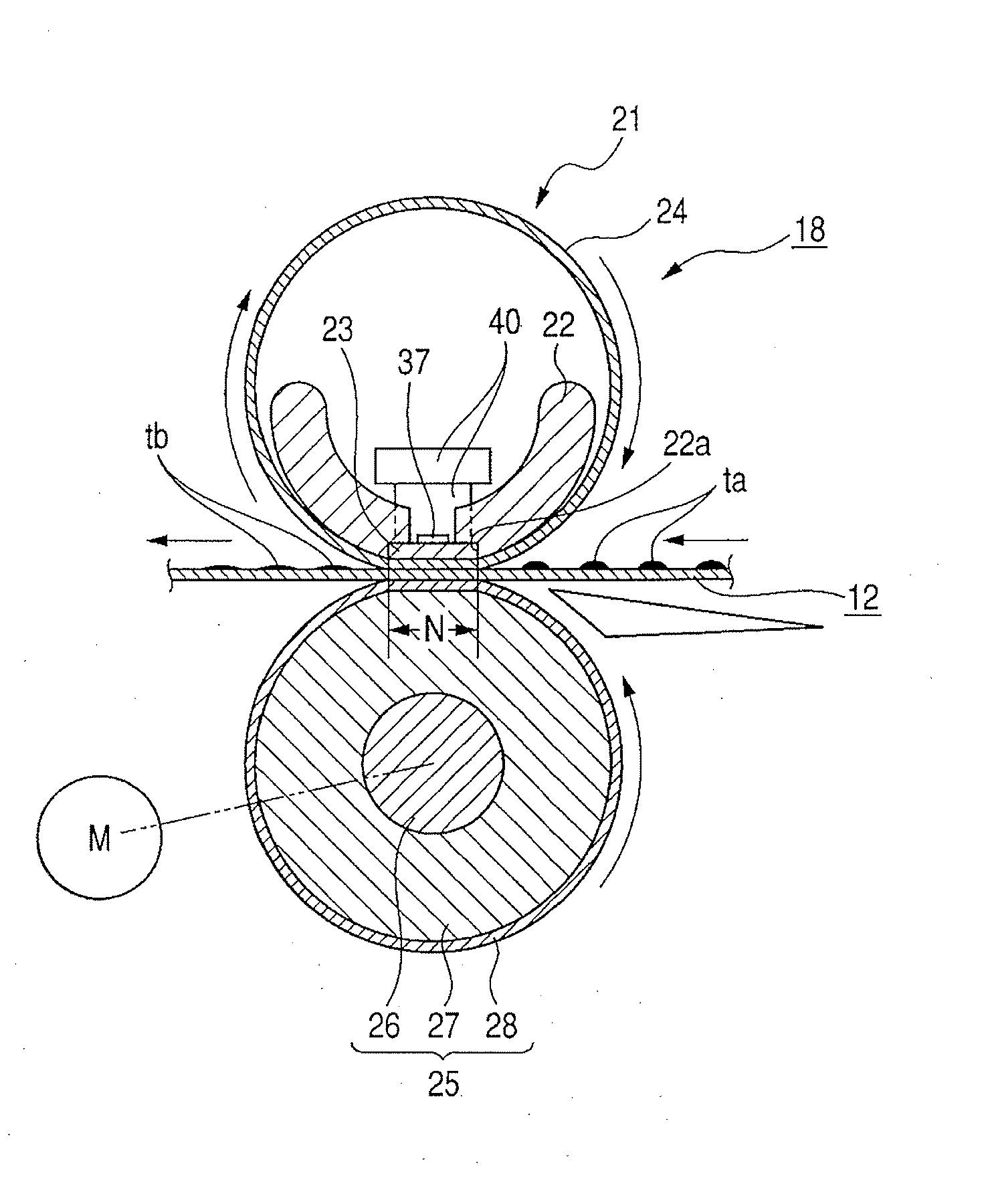
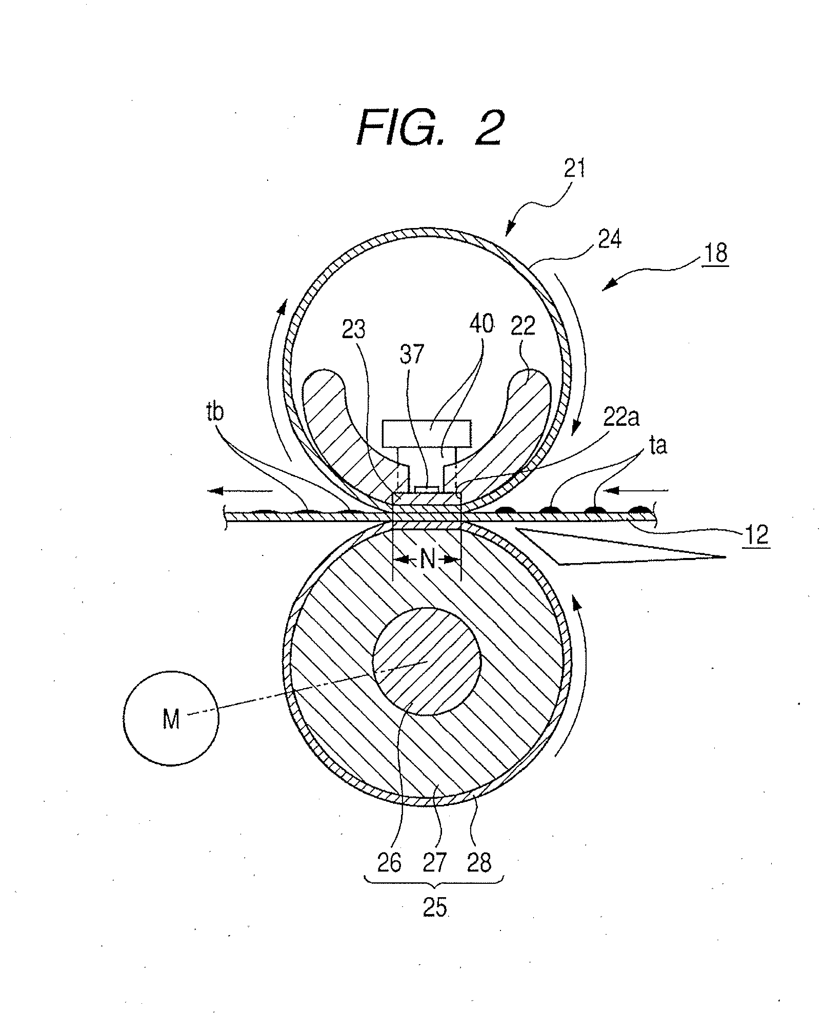
Heater having heat generating resistor on substrate and image heating apparatus mounting heater thereon

a heat generating resistor and substrate technology, applied in the field of image heating apparatus, can solve the problems of increasing cost, and achieve the effect of suppressing the increase in cost and resisting stress

Active Publication Date: 2007-08-09
CANON KK
View PDF18 Cites 17 Cited by
  • Summary
  • Abstract
  • Description
  • Claims
  • Application Information

AI Technical Summary

Benefits of technology

[0015] The present invention is made in consideration of the abovementioned problems, and an object of the present invention is to provide a heater which has resistance against stress while suppressing increase in cost, and an image heating apparatus using such a heater.

Problems solved by technology

However, if the reinforcing layer is provided on the whole surface of the substrate, the cost will be increased.

Method used


Image

  • Heater having heat generating resistor on substrate and image heating apparatus mounting heater thereon
  • Heater having heat generating resistor on substrate and image heating apparatus mounting heater thereon
  • Heater having heat generating resistor on substrate and image heating apparatus mounting heater thereon

Examples


first embodiment

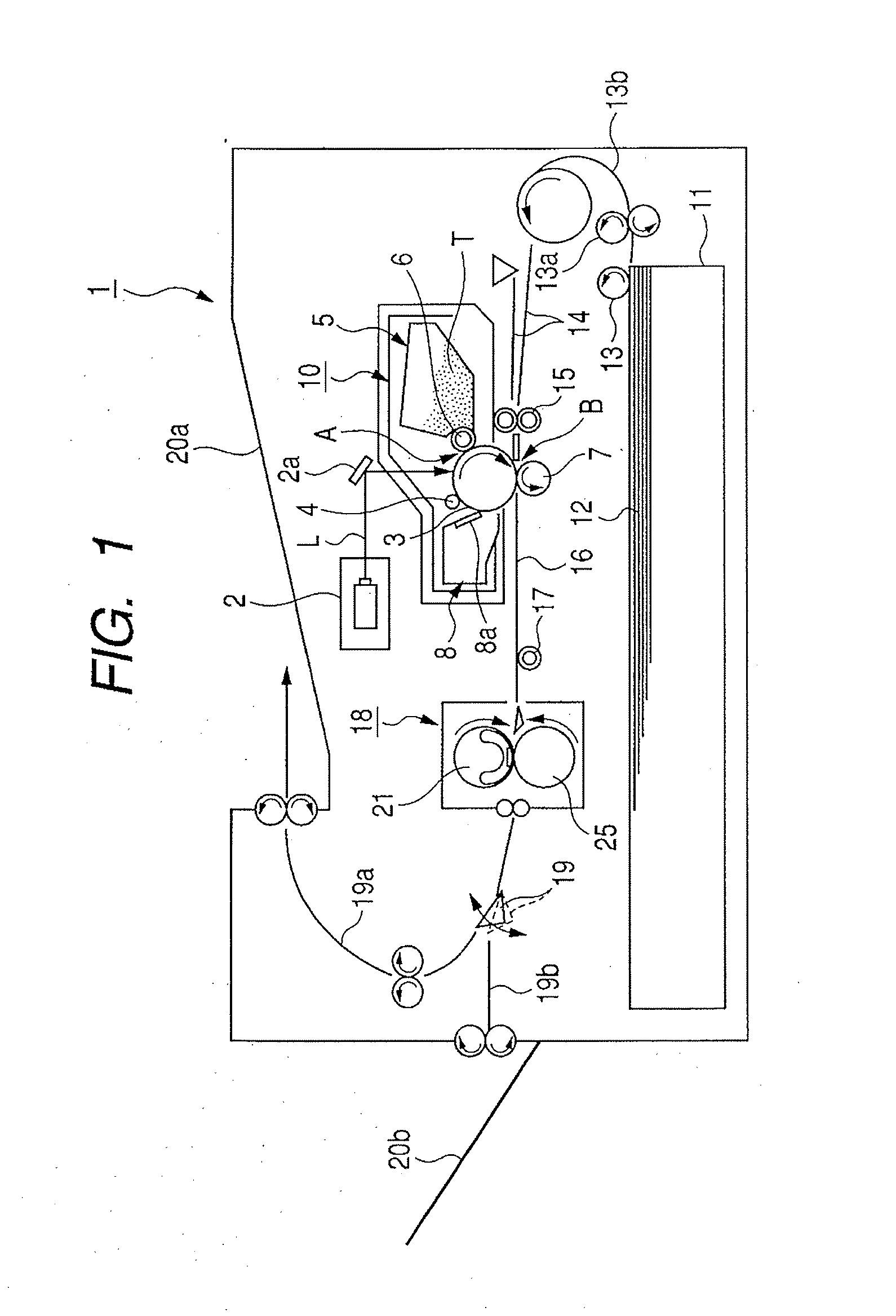
[0033]FIG. 1 shows a schematic construction of an image forming apparatus having an image heating apparatus according to an embodiment of the present invention. In this embodiment, the image forming apparatus is an electrophotographic laser beam printer. Hereinbelow, a whole construction of the laser beam printer will be described.

[0034] (1) Whole Construction of Image Forming Apparatus

[0035] In FIG. 1, an image forming apparatus 1 according to this embodiment comprises a scanner unit 2 as exposure means for illuminating and scanning a laser beam L emitted in response to image information.

[0036] Further, the image forming apparatus 1 includes a process cartridge 10 removably mounted to a main body of the image forming apparatus. The process cartridge 10 incorporates main image forming means therein. Namely, the process cartridge 10 includes an electrophotographic drum-shaped photosensitive member (referred to as “photosensitive drum” hereinafter) 3 as an image bearing member, and...

second embodiment

[0099] Next, a second embodiment of the present invention will be explained. According to this second embodiment, in a heater comprising three heat generating resistors and in which and heat generation amounts of the heat generating resistors are changed continuously, thicknesses of substrate reinforcing members disposed on a rear surface of the heater are varied along the longitudinal direction (Namely, the thickness of the substrate reinforcing layer is changed in accordance with a resistance value per unit length of the second heat generating resistor). With this arrangement, the increase in temperature of the sheet non-passing portion of the heater can be prevented and, at the same time, the heater crack during the thermal overrun can be prevented.

[0100] A heater 23 used in the second embodiment is shown in FIGS. 9A to 9D. FIG. 9A shows a sheet side surface of a heater, FIG. 9B shows a sheet side surface of a heater which does not have a protective layer like glass), FIG. 9C sh...


PUM


Abstract

The heating apparatus comprises a substrate extending in one direction and a plurality of heat generating members provided on one surface of the substrate along a longitudinal direction thereof and wherein at least one of the plural heat generating members has heat generating regions having different heat generation amount per unit length in the longitudinal direction, substrate reinforcing members are provided on the other surface of the substrate in correspondence to the high heat generating regions provided on one surface of the substrate. By the virtue of the invention, cost can be reduced, emergency safety upon occurrence of overrun of a CPU can be achieved, and increase in temperature of a sheet non-passing portion can be suppressed.

Description

BACKGROUND OF THE INVENTION [0001] 1. Field of the Invention [0002] The present invention relates to an image heating apparatus suitable to be used as a thermal fixing apparatus mounted to an image forming apparatus such as a copier, a printer or the like, and more particularly, it relates to a heater having a heat generating resistor on a substrate, and an image heating apparatus mounting such a heater thereon. [0003] 2. Description of the Related Art [0004] In the past, in image forming apparatuses such as electrophotographic copiers, laser beam printers and the like, a latent image corresponding to target image information was formed on an image bearing member by image forming process means, and, from the latent image, a visual image (toner image) was formed by using toner including resin having a thermally-soluble property. Then, the toner image was transferred onto a surface of a recording material such as a transferring paper, directly, or indirectly via an intermediate transf...

Claims


Application Information

Patent Timeline
IPC IPC(8): B41J2/01
CPCG03G15/2042H05B3/0095
Inventor MAKIHIRA, TOMOYUKIMAEDA, MASAFUMI
Owner CANON KK
Learn More