Light absorbing elements

a technology of light absorbing elements and shielding articles, which is applied in outdoor lighting, lighting applications, lighting and heating apparatus, etc., can solve the problems of unfavorable use of lighting, and glare, so as to prevent glare disabling, excellent cut off shielding, and improve viewing conditions

Inactive Publication Date: 2007-08-09
ELLEMOR JOHN WARWICK
View PDF9 Cites 17 Cited by
  • Summary
  • Abstract
  • Description
  • Claims
  • Application Information

AI Technical Summary

Benefits of technology

[0044] Another application presents a skylight, light emitting panels are used on multi-faceted shapes such as a three sided pyramid may be assembled from transparent panels, each incorporating thin opaque components, that are reflective on one surface and light absorbent on the other surface. The angles can vary in cross section and / or longitudinal according to requirements at different latitudes which can require early and late in the day high light input and a limited input during the centre of the day's heat or a day long constant input. An assembly of this form is preferably mounted upon a circular shaped mounting section, so as to be capable of rotation about a vertical or near vertical axis, so that in one application it is capable of being oriented so that one panel faces towards the pole in the hemisphere in which it is located with either a third light admitting panel or a configured sheet that re-reflects incoming light from the other panels downwards. The two panels positioned adjoining the equatorial facing corner would enable, particularly toward the higher latitudes, admittance of light from the East and the West. Alternately the reflective surfaces can be positioned to limit the light and thus heat input during the middle hours of the day in higher temperature locations to present a more comfortable situation.
[0045] In addition, examples of excellent cut off shielding and using the reflected component to maximum advantage can relate to a game of tennis after dark,_wherein by applying this disclosure, light from both ends can provide a cut off so a player will not sight the opposite end's light source even when standing next to the net, while lights installed at each end of the net will illuminate the wedge shaped, otherwise dark area above head height.
[0046] The cut off advantage can also relate to under water lighting for Swimming Pools, providing Glare free conditions for those relaxing around the pool by exposing them only to light diffused under water sectors, the light shields can have their shielding components angled and the refraction of the shields in combination with the refraction of the water arranged to only be observed by diving under the pool's surface. These examples and many other applications, prevent Glare disabling or Glare discomfort annoying those exposed and where Sharp cut off and / or selectively directed additional light vastly improves viewing conditions.

Problems solved by technology

How the contrast caused by direct or reflected light within the normal field of view effects an observer depends on how well surfaces absorb light, too glossy even if the colour is black it won't prevent specular glare at reflective angles, and there are problems if a light absorbent texture is difficult to clean and maintain if open to atmosphere, alternately if the shielding article is used for observation there through or provides a combination of both functions, it will have an effect on how well people can work within their environment and how comfortable they feel, when our eyes look at a task, they adapt to the brightness or luminance of that area, as our eyes leave the task and look at an area of different luminance, there is a sudden loss in the eye's ability to see contrast details in the new area until the eye can adjust to the new light levels.
Another form of light shield commonly used with fluorescent light sources comprises a sheet of clear plastic featuring a prismatic configuration, whilst such sheets do transmit a high proportion of light in a vertical direction, they still present a considerable level of glare, particularly at the junction of prisms and where angles meet.
The slats of the blind however being exposed to the atmosphere collect a great deal of dust, they also present annoying reflections from the glossy and usually lighter colours, the slats are also often of a. lightweight construction which have to be curved for strength and this results in a wider interruption of the view through the window, further the slats often have a gloss surface which means that direct sunlight will reflect from some point on the curve if they are positioned near to horizontal, and thus looking through them distracts one from enjoying the view.
In many situations current luminaires lack sufficient directional control and create unwanted glare with little if any effective shielding being used and many luminaires operating near Computer Screens or above high gloss or white surfaces that reflect high light levels back to the user, interfering with the tasks in hand.
It can provide absorption never before permanently achieved and present secondary reflections so unobtrusive that near by exposed surfaces won't provide any indication where the source is located and create a situation as comfortable and relaxing as an overcast sky and present viewing situations without shadows.

Method used


Image

  • Light absorbing elements
  • Light absorbing elements
  • Light absorbing elements

Examples


Embodiment Construction

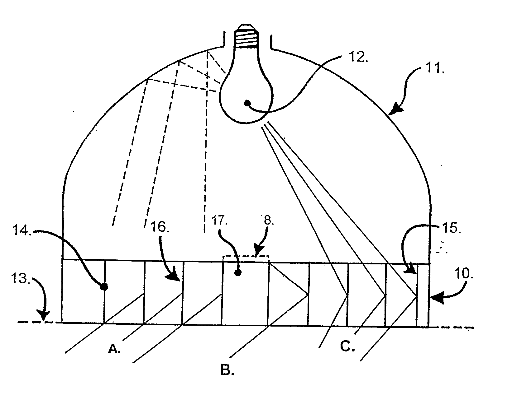
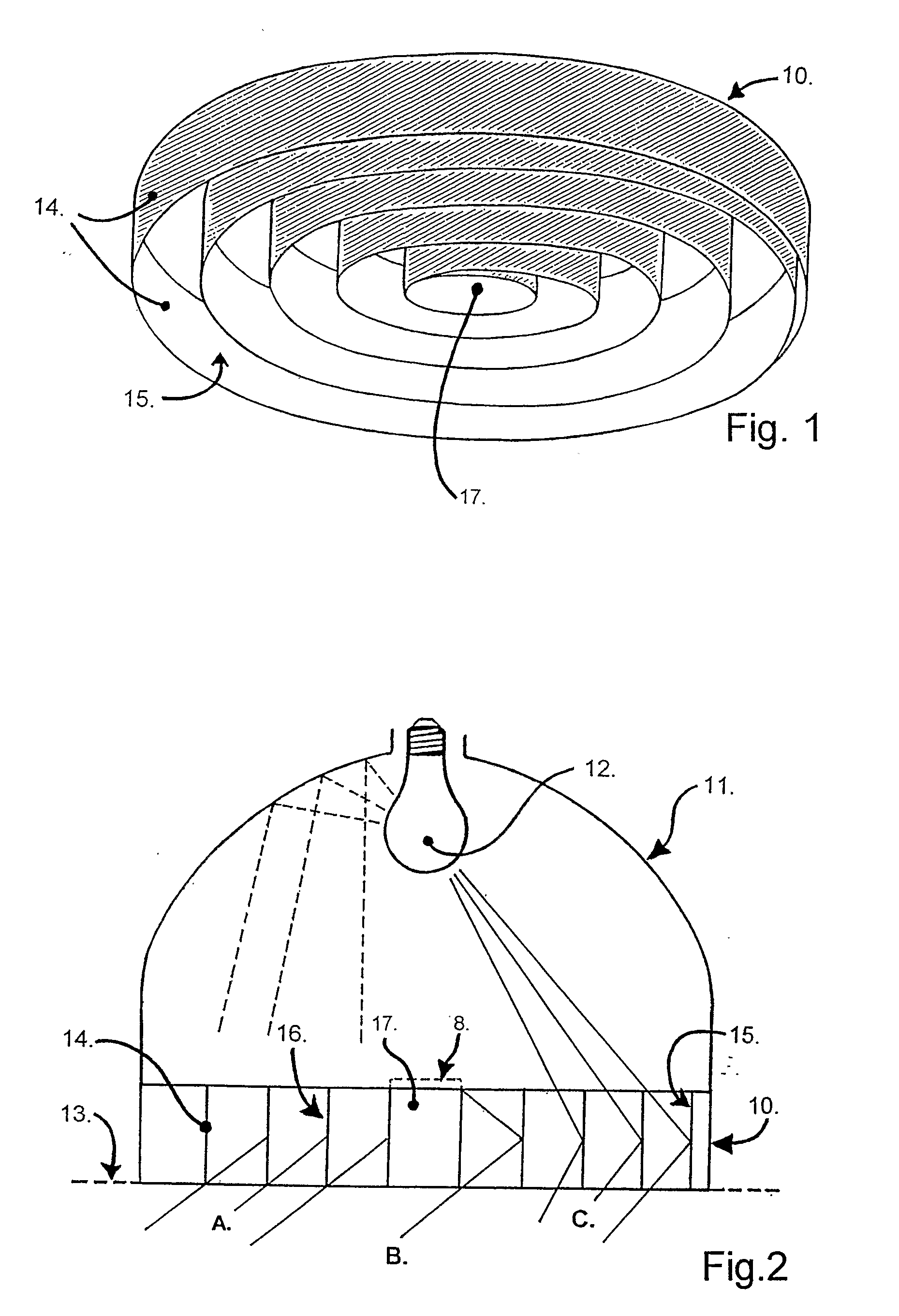
[0061]FIGS. 1. and 2. illustrate one application of the invention in the form of a light shielding device 10. in a recessed light fitting 11. having a conventional light source 12. which for example may be an incandescent lamp and which is supported rearward of the shielding device 10. The body and fixing details of the light fitting 11 are not shown. The light fitting 11. may be mounted in or on a ceiling, wall, floor or other surface and most suitably is recessed such that the lower edge of the shielding device 10. is flush with the surface 13. of the ceiling, wall or floor (shown in dotted outline). The shielding device 10. is formed of a single length of strip material 14. suitably of aluminium which is formed into a spiral shape such that the major dimension of the strip is parallel to the plane containing the central axis of the spiral and substantially normal to the surface 13. The strip material 14. has on its inner face 15. that is facing towards the centre of the spiral, a...


PUM


Abstract

Light shielding devices are created from opaque, light absorbing strips (39), created by coating the strips (38,39) with a, preferably, black light-absorbing coating, and arranging the strips to extend to the surface or surfaces of a transparent material in which the strips are encased, enclosed or embedded. Strips (38, 39) installed in a parallel arrangement provide a low glare collimating effect to transmitted light for either illumination or observation. Selected sides of a plurality of strips (38) may have a reflective finish such that the arrangement of the strips may either enhance the collimating effect or alternatively create a dispersing effect. Disclosed embodiments include: an overhead incandescent light shield, a bollard light shield, an overhead fluorescent light shield, a window shield, a vehicle dashboard, a pool light cover, and sunglasses.

Description

TECHNICAL FIELD [0001] Herein is disclosed a method of construction and the shielding articles made thereby that will provide an observation function by causing the least interference when viewing a desired scene, subject matter or a task in hand there through. A similarly constructed shielding article can be used to distribute natural or artificial light transmitted from rearward thereof, providing an illuminating function by confining the light distribution there from to any preferred extent, the thus completed articles can also combine both observation and illumination together in a common article with both functions using it entirely, or a part or parts thereof providing individual functions. [0002] The forgoing functions will be possible by combining just two physical opaque components, both can feature in a variety of ways, and when combined the transparent material may either be an encapsulating solid or a multiplicity of pieces or fluid in a transparent container, that in ag...

Claims


Application Information

Patent Timeline
Patent Type & Authority Applications(United States)
IPC IPC(8): G02B27/00E06B9/24F21S8/00F21S8/02F21S11/00F21V11/00F21V11/02F21V11/06
CPCE06B9/24F21S8/02F21S8/022F21S11/00F21Y2113/00F21V11/02F21V11/06F21W2111/00F21W2131/109F21V11/00F21Y2103/00
Inventor ELLEMOR, JOHN WARWICK
Owner ELLEMOR JOHN WARWICK
Why Eureka
Try Eureka