
Compositive wave plate

a composite wave plate and wave plate technology, applied in the field of wave plates, can solve the problems of direct incidence of divergent light on the phase shift problem of the composite wave plate, and the long front monitor

Inactive Publication Date: 2007-08-09
TOYO TSUSHINKI
View PDF13 Cites 4 Cited by
  • Summary
  • Abstract
  • Description
  • Claims
  • Application Information

AI Technical Summary

Problems solved by technology

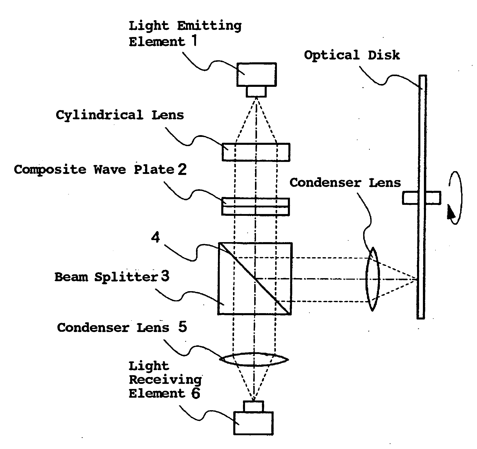
In the optical head device of such a configuration as depicted in FIG. 7, however, the distance from LD1 to the light receiving element 6 of the front monitor is long, constituting an obstacle to miniaturization of the optical head device.
Accordingly, since the desired phase difference by the composite plate is added with a further phase shift, direct incidence of divergent light on the composite wave plate presents a problem of the phase shift by the incidence angle dependence.

Method used


Image

  • Compositive wave plate
  • Compositive wave plate
  • Compositive wave plate

Examples


first embodiment

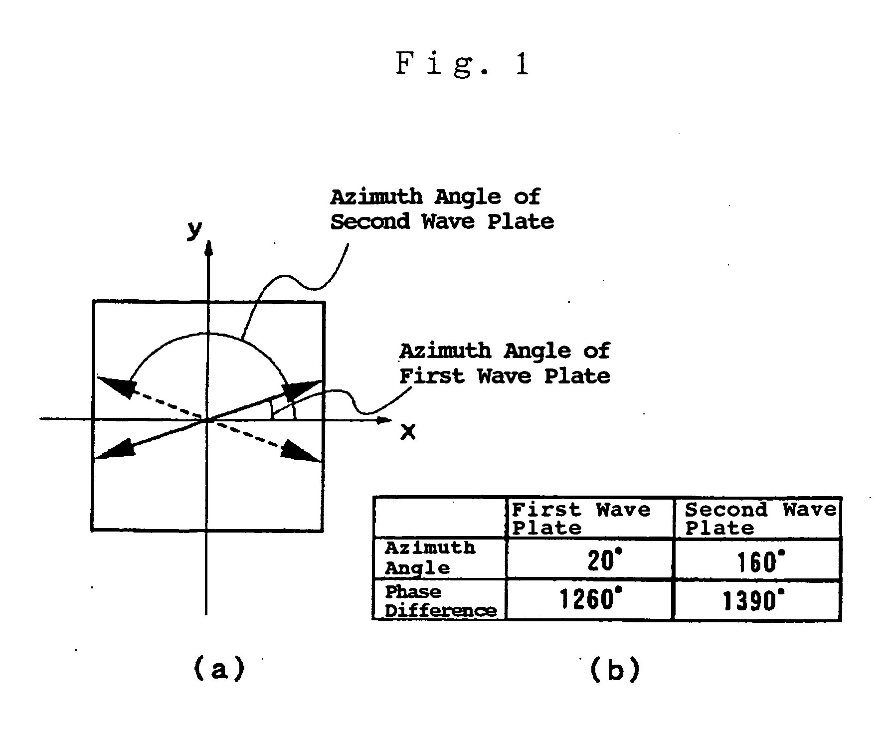
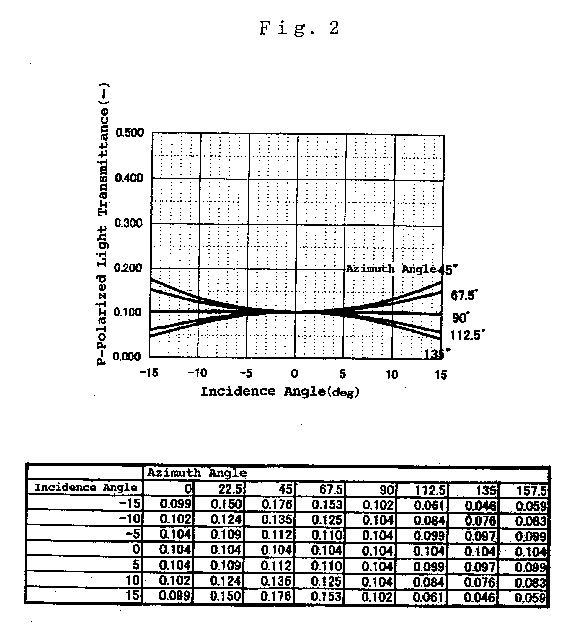
[0031]FIG. 1 illustrates the structure of a composite wave plate according to the present invention, FIG. 1(a) being a plan view of the composite wave plate as viewed from the direction of incidence of light thereon, and FIG. 1(b) being a table showing the differences in the azimuth angle and phase between the first and second wave plates to be laminated. FIG. 2 shows the dependence of the composite wave plate on incidence angle, from which it can be seen that variations in the transmittance of the P-polarized light with the incidence angle of divergent light has been sharply improved as compared with the incidence angle dependence in the prior art described in FIG. 11.

second embodiment

[0032]FIG. 3 illustrates the structure of a composite wave plate according to the present invention, FIG. 3(a) being a plan view of the composite wave plate as viewed from the direction of incidence of light thereon, and FIG. 3(b) being a table showing the differences in the azimuth angle and phase between the first and second wave plates to be laminated. FIG. 4 shows the dependence of the composite wave plate on incidence angle, from which it can be seen that variations in the transmittance of the P-polarized light with the incidence angle of divergent light has been sharply improved as compared with the incidence angle dependence in the prior art described in FIG. 11.

[0033] The inventor of this application hit upon an idea that he composite wave plates of the first and second embodiment of the present invention could be computed by mathematical calculations based on the conditional expression described below.

[0034] Next, the optical operation of the composite wave plate according...


PUM


Abstract

The invention is intended to solve the problem of a phase shift by the incidence angle dependence of a composite wave plate which is caused when divergent light is incident directly thereon because of occurrence of a phase shift in addition to a desired phase difference of the composite wave plate. The composite wave plate is composed of two laminated wave plates, and respective parameters are set such that: letting θ1 represent the azimuth angle of the optical axis of the first wave plate with respect to the plane of polarization of incident light thereon in the Poincare sphere representation, θ2 represent the azimuth angle of the optical axis of the second wave plate with respect to the plane of polarization of incident light thereon in the Poincare sphere representation, Γ1 represent a phase rotation about the axis of rotation R1 of the first wave plate in the Poincare sphere representation, and Γ2 represent a phase rotation about the axis of rotation R2 of the second wave plate in the Poincare sphere representation,θ2−θ1≠π / 2;and that a phase difference ΓT of the composite wave plate satisfiesΓT=(2×θ1−π / 2)cos Γ1+(2×θ2−π)cos Γ2.

Description

BACKGROUND OF THE INVENTION [0001] 1. Field of the Invention [0002] The present invention relates to a wave plate for use in an optical head or similar optical device that projects a light spot onto a CD, DVD, or similar disk-shaped storage medium to record thereon information or reproduce therefrom recorded information and, more particularly, to a wave plate of improved dependence on the angle of incidence thereon of divergent light, and an optical head using the wave plate. [0003] 2. Background Art [0004] An optical disk recording and reproducing apparatus that uses laser light to record information on and reproduce information from a CD, DVD, or similar disk-shaped storage medium is provided with an optical head device that projects a spot of laser light emitted from a laser light source onto the data-bearing surface of the storage medium to record thereon information and reproduce therefrom information. [0005] As is well-known in the art, the optical head device has a semiconduc...

Claims


Application Information

Patent Timeline
IPC IPC(8): G11B7/00G02B5/30G11B7/125G11B7/1263G11B7/135G11B7/1365
CPCG02B5/3083G11B7/1365G11B7/1263
Inventor OOTO, MASAYUKI
Owner TOYO TSUSHINKI
Learn More