
Central joint for a steering triangle of moto vehicles

a central joint and steering triangle technology, applied in suspensions, couplings, transportation and packaging, etc., can solve the problem of no non-uniform bracing, and achieve the effect of improving the sealing function of the central joint, improving the design and consequently the assembly effor

Inactive Publication Date: 2007-08-09
ZF FRIEDRICHSHAFEN AG
View PDF12 Cites 7 Cited by
  • Summary
  • Abstract
  • Description
  • Claims
  • Application Information

AI Technical Summary

Benefits of technology

[0005] The object of the present invention is therefore to improve a central joint for a steering triangle such that the design and consequently the assembly effort are simplified and, moreover, improved sealing function of the central joint is created.
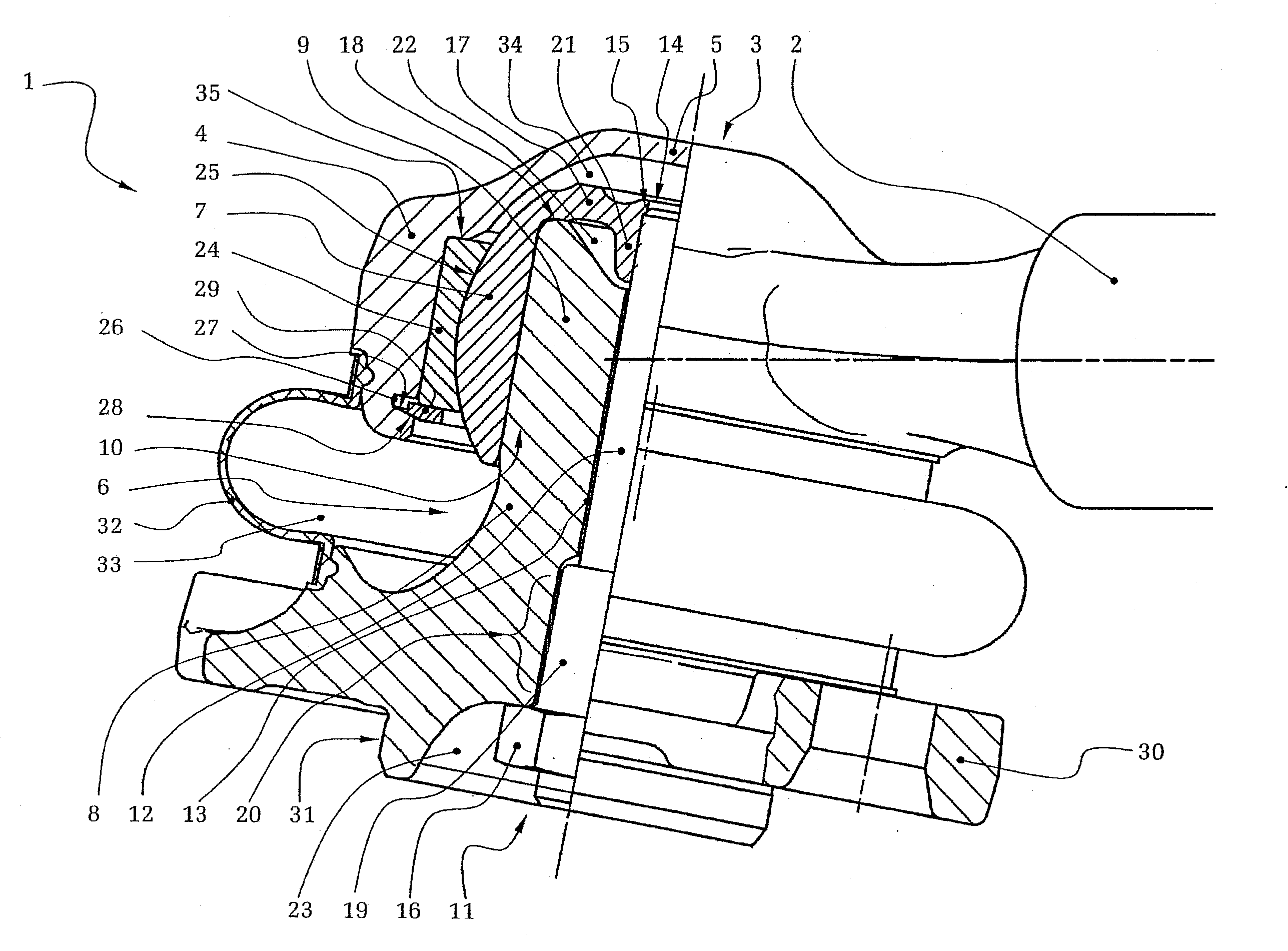
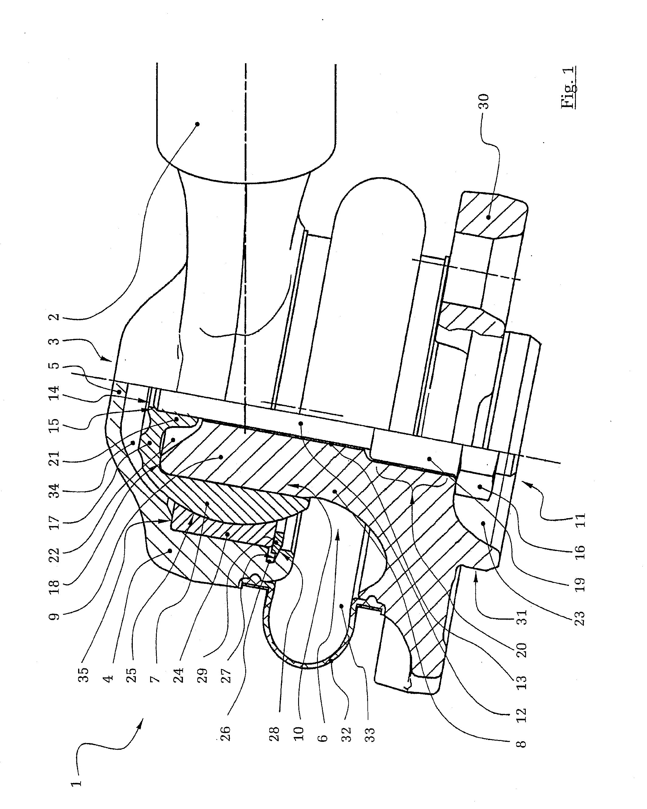
[0006] According to the invention, a central joint is provided for a steering triangle of motor vehicles with a ball pivot mounted in a pivotingly and rotatingly movable manner in a joint housing, wherein the joint housing is formed from a joint housing body and a joint housing bottom and the ball pivot is formed from a tower-shaped ball pivot body and a joint ball attached to the ball pivot body. The joint housing body and the joint housing bottom are made in one piece. As a result, separate components as well as partition lines in the area of the joint housing are avoided, so that the assembly effort can be considerably simplified compared to the state of the art and, moreover, a sealed joint housing can be guaranteed because of the lack of sealing joints. Especially in the case of utility vehicles, the area in which the steering triangle is connected to the axle is increasingly compromised by dirt and moisture, so that the sealing function is of increased significance.
[0007] In an advantageous embodiment, the joint ball and the ball pivot body are connected to one another by means of a screw connection, the ball pivot body being cylindrical on its end facing the joint ball and this end being inserted into a likewise cylindrical recess of the joint ball. The diameter of the cylindrical end of the ball pivot body is larger here than the inside diameter of the cylindrical recess of the joint ball, so that there is a uniform surface pressure between the joint ball and the ball pivot body over the area in which they are in contact together, with a slight bracing of the force fit without appreciable stress peaks, as a result of which the permissible operating loads can be considerably increased compared to, for example, a conical force fit. Thus, there also is no notch effect, which could shorten the service life of the tower-shaped ball pivot. Moreover, the joint ball is also expanded uniformly in the radial direction due to the uniform surface pressure, so that no non-uniform bracing can develop in the sliding pair formed by the bearing shell and the joint ball. The bearing shell is rather prestressed uniformly.
[0009] The screw connection is advantageously formed by means of a threaded pin, which passes through a through hole of the ball pivot body, cooperates at one end with a threaded hole in the joint ball and is fixed on the side facing away from the joint ball with a threaded nut in relation to the ball pivot body. The threaded hole in the joint ball advantageously has a shoulder, against which the threaded pin is screwed into the threaded hole, the threaded hole being arranged within a material thickening formed in the bottom of the joint ball, which said material thickening is located within a recess of the cylindrical end of the ball pivot body in the mounted state of the joint ball. The threaded nut is in turn likewise advantageously arranged in the mounted state in a recess, which is located on the side of the ball pivot body facing away from the cylindrical end. For simplified mounting and removal of the central joint, the threaded nut has, moreover, an extended carrying threaded area, which is located within an expanded area of the through hole in a preferred embodiment. This arrangement makes possible a height-adjustable design, because the screw connection is arranged essentially completely within the components to be connected, and, moreover, the joint ball has an increased overlap with the tower-shaped ball pivot body. The extended carrying threaded area advantageously increases, moreover, the load-bearing capacity of the screw connection. Furthermore, in an advantageous manner, there is a full radial overlap of the bearing surface between the bearing shell and the joint ball with the contact surface of the joint ball and the ball pivot body in the axial extension of the bearing shell.
[0010] To improve the sliding properties between the bearing shell and the joint ball, a sliding layer, preferably one made of a plastic, may be arranged between the bearing shell and the joint ball.

Problems solved by technology

Especially in the case of utility vehicles, the area in which the steering triangle is connected to the axle is increasingly compromised by dirt and moisture, so that the sealing function is of increased significance.
Moreover, the joint ball is also expanded uniformly in the radial direction due to the uniform surface pressure, so that no non-uniform bracing can develop in the sliding pair formed by the bearing shell and the joint ball.

Method used


Image

  • Central joint for a steering triangle of moto vehicles
  • Central joint for a steering triangle of moto vehicles

Examples


Embodiment Construction

[0015] Referring to the drawings in particular, FIG. 1 shows a sectional view of a central joint 1 of a steering triangle, which connects two struts 2 (only one strut being shown here) to one another via a joint housing 3. The joint housing 3, built up from a joint housing body 4 and a joint housing bottom 5, is made in one piece, for example, from a metallic cast material. A ball pivot 6 is arranged in a rotatingly and pivotingly movable manner in the joint housing 3, the ball pivot 6 having ajoint ball 7 and a ball pivot body 8. The ball pivot body 8 has a cylindrical end 9, which is inserted into a likewise cylindrical recess 10 of the joint ball 7. The cylindrical end 9 of the joint ball body 8 has a larger diameter than the cylindrical recess 10 of the joint ball 7, so that there is a press fit between the joint ball 7 and the ball pivot body 8. Instead of the cylindrical shape of the recess 10 and of the end 9 of the ball pivot body 8, it is also possible to select any other p...


PUM


Abstract

A central joint (1) for a steering triangle of motor vehicles, especially utility vehicles, has a ball pivot (6) accommodated in a joint housing (3), wherein the joint housing (3) is formed from a joint housing body (4) and a joint housing bottom (5) and the ball pivot (6) is formed from a tower-shaped ball pivot body (8) and a joint ball (7) attached to the ball pivot body (8). The ball pivot (6) is mounted in a bearing shell (24) fixed in the joint housing (3) in a pivotingly and rotatingly movable manner. The joint housing (3) is formed from the joint housing body (4) and the joint housing bottom (5) in one piece.

Description

CROSS REFERENCE TO RELATED APPLICATIONS [0001] This application is a United States National Phase application of International Application PCT / DE 2005 / 001010 and claims the benefit of priority under 35 U.S.C. § 119 of German Patent Application DE 10 2004 029 581.6 filed Jun. 18, 2004, the entire contents of which are incorporated herein by reference. FIELD OF THE INVENTION [0002] The present invention pertains to the mounting of steering triangles for guiding rear axles, especially of utility vehicles, preferably for the central mounting of the steering triangle on the rear axle. BACKGROUND OF THE INVENTION [0003] Such steering triangles are used especially to guide rear axles of utility vehicles, wherein two struts, which are connected to the vehicle body in an articulated manner at one end and are connected at their other end to the rear axle of the vehicle by means of a central joint. The two struts are connected via a common joint housing, in which a joint ball, which is rigidly...

Claims


Application Information

Patent Timeline
Patent Type & Authority Applications(United States)
IPC IPC(8): F16C11/00B60G7/00F16C11/06
CPCB60G7/005B60G2200/315B60G2204/148Y10T403/32704F16C11/069F16C11/0609B60G2204/416F16C2326/05
Inventor KUNZE, RALFKNOPP, SOREN
Owner ZF FRIEDRICHSHAFEN AG
Learn More