Low cost safety lancet

Active Publication Date: 2007-08-09
FACET TECH LLC
View PDF21 Cites 118 Cited by
  • Summary
  • Abstract
  • Description
  • Claims
  • Application Information

AI Technical Summary

Benefits of technology

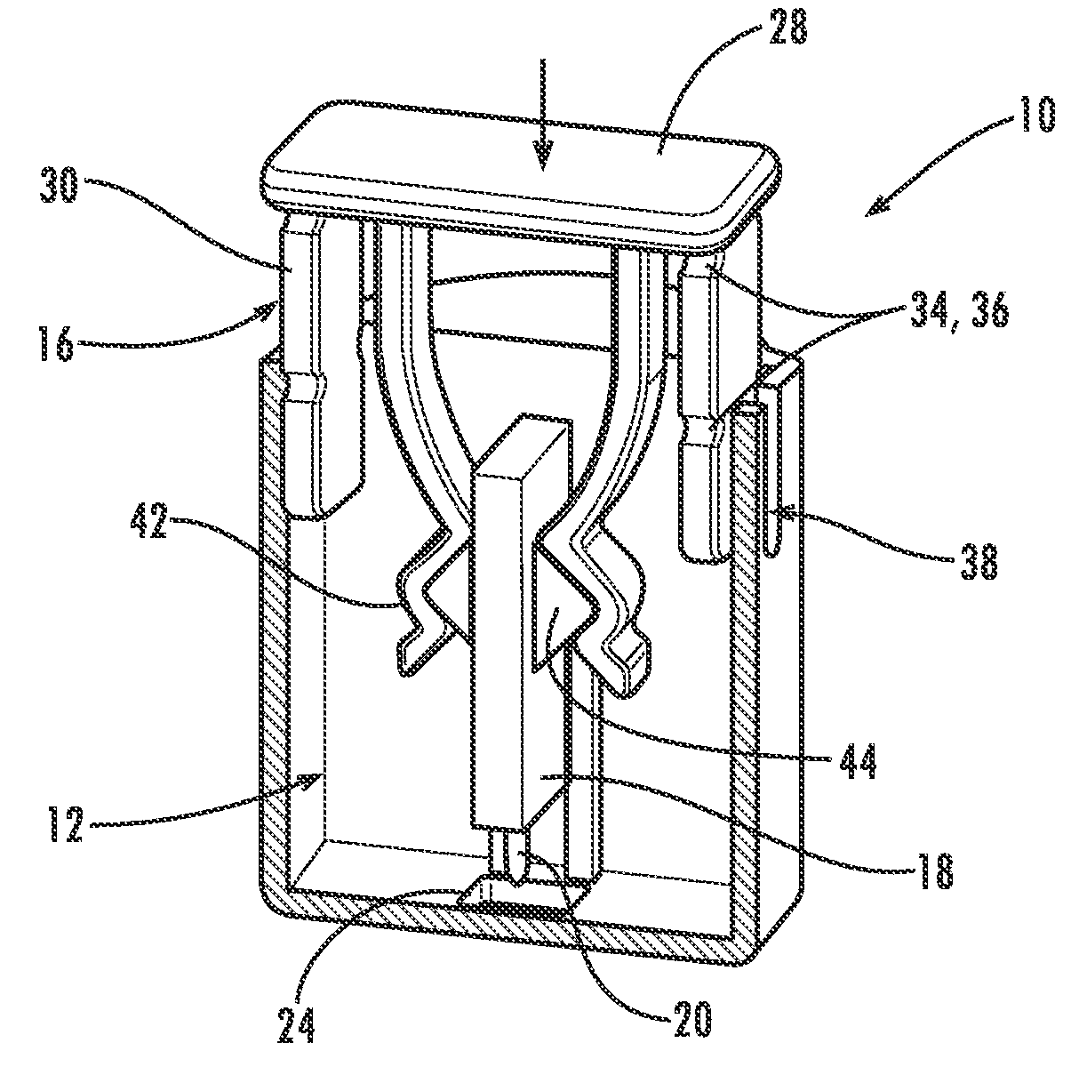
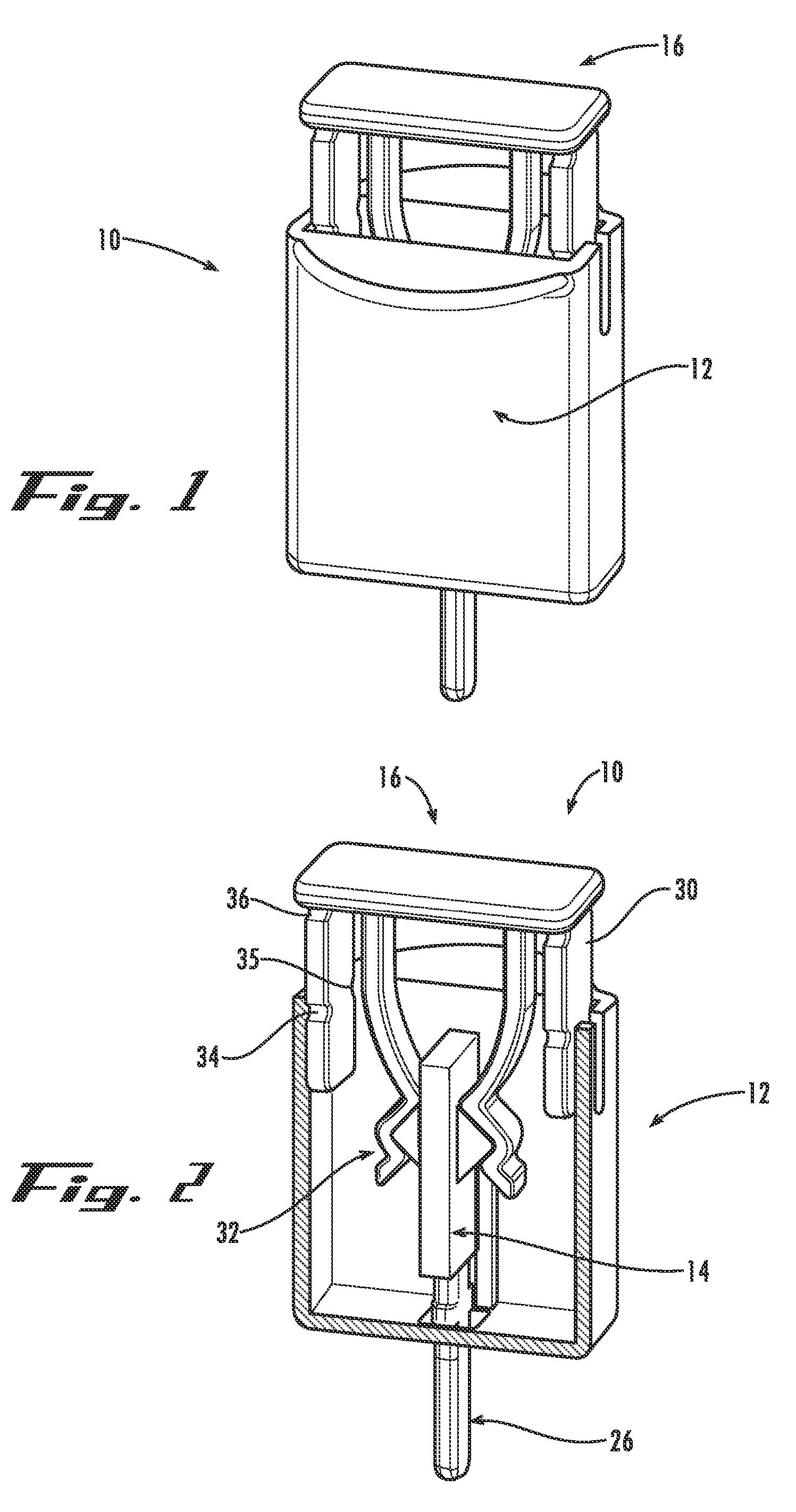
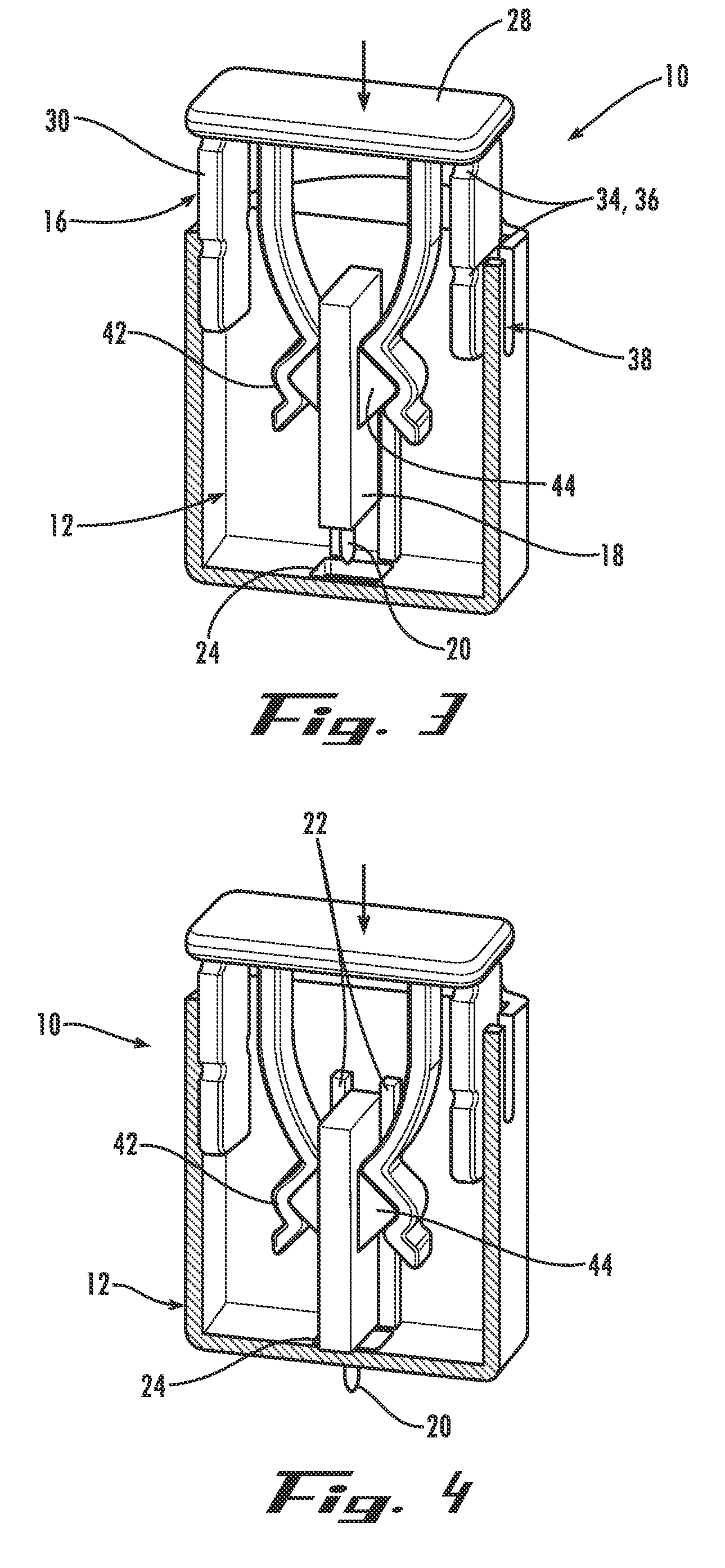
[0014] In a third example embodiment, the ramped protrusions together have the shape of an inverted heart or letter “V”. And in a fourth example embodiment, the ramped protrusions together are delta-shaped. In these configurations, each of the ramped protrusions are generally wedge-shaped and have lock surfaces that prevent the lancet from being pulled from engagement with the control assembly when the user pulls the sterility cap off for use.
[00

Problems solved by technology

Accordingly, single-use lancing devices oftentimes include a disabling mechanism to prevent accidental or intentional re-use of the device.
However, most known single-use lancing devices are too costly and

Method used


Image

  • Low cost safety lancet
  • Low cost safety lancet
  • Low cost safety lancet

Examples


Example

[0050]FIG. 8 shows a lancing device according to a second example embodiment of the invention that implements this same inventive concept. The lancing device 110 has a housing 112, a lancet 114, and an activation / retraction control assembly 116. In this embodiment, the lancet control fingers 132 include the ramped protrusions 144 and the lancet body 118 includes the notched sections 142 and the angled sections 140.

[0051]FIGS. 8-11 show the operation of the lancing device 110, which occurs in substantially the same fashion as the operation of the lancing device 10 of the first embodiment. In FIG. 8, the activation / retraction control assembly 116 is being pressed to activate the lancing device. In FIG. 9, the lancet 114 is stopped in a fully extended position for puncturing, and the control assembly 116 is free to continue traveling. In FIG. 10, the control assembly 116 is stopped. And in FIG. 11, the lancet 114 is retracted by the control assembly 116 back into the housing 112.

Example

[0052]FIG. 12 shows part of a lancing device according to a third example embodiment of the invention that is similar to the first example embodiment. In this embodiment, however, the lancet body 218 includes ramped protrusions 244 that together have the general shape of an inverted “V” or heart. And the lancet control fingers 232 have two notched sections 242 that cooperatively conform generally to the shape of the ramped protrusions 244. In other words, the ramped protrusions 244 have first angled releasable engagement surfaces 244a and second lock surfaces 244b, preferably at an angle to each other of ninety degrees or less. And the notched sections 242 have first angled releasable engagement surfaces 242a and second lock surfaces 242b, preferably at an angle to each other of ninety degrees or less. In this way, the second lock surfaces 242b of the notched sections 242 form a positive one-way lock with the second lock surfaces 244b of the ramped protrusions 244. So when the user ...

Example

[0053]FIGS. 13 - 18 show a lancing device 310 according to a fourth example embodiment of the invention that is similar to the third example embodiment just described. Thus, the lancing device 310 includes a housing 312, a control assembly 316 with control fingers 332 having notched sections 342 and angled retraction sections 340, and a lancet 314 having a body 318 and ramped protrusions 344. In this embodiment, however, the ramped protrusions 344 together are delta-shaped. Similarly to the third embodiment, the second lock surfaces 342b of the notched sections 342 form a positive one-way lock with the second lock surfaces 344b of the ramped protrusions 344 so that removing the sterility cap 326 does not pull the lancet's ramped protrusions 244 from engagement with the lancet control finger's notched sections 242.

[0054] In addition, the sterility cap 326 defines one or more stop surfaces 346 that extend beyond the dimension of the housing's lancing opening 324 to prevent the steril...


PUM


Abstract

A lancing device has a housing, an activation/retraction control assembly, and a lancet. The control assembly and the housing have cooperating engagement structures such as detents that disengage after a predetermined launch force is applied to the control assembly. In this way, the lancet is driven to its puncturing position without the use of a drive spring. In addition, the control assembly and the lancet have cooperating releasable engagement structures such as notched sections and tamped protrusions that disengage when the lancet reaches its puncturing position, thereby freeing the lancet from the control assembly. And the control assembly has angled retraction structures that engage the freed lancet to bias it back safely into the housing.

Description

CROSS REFERENCE TO RELATED APPLICATION [0001] This application claims the priority benefit of U.S. Provisional Patent Application Ser. No. 60 / 582,867 filed on Jun. 25, 2004, which is hereby incorporated herein by reference in its entirety for all purposes. Technical Field [0002] The present invention relates generally to medical devices and, more particularly, to a lancing device for penetrating the skin of a human or animal subject for sampling of blood and / or other body fluids. BACKGROUND OF THE INVENTION [0003] Lancing devices are used to penetrate the skin of a subject and obtain a sample of blood or other body fluid, as in the testing of blood sugar levels by diabetics. Typically, a lancet having a sharp point is translationally mounted within a housing portion of a lancing device. The lancet is driven by a spring or other biasing means to cause the sharp point to extend a small distance through an opening in the housing and into the subject's skin, creating a wound from which ...

Claims


Application Information

Patent Timeline
IPC IPC(8): A61B17/32
CPCA61B5/1411A61B5/1433A61B5/151A61B5/15142A61B5/150022A61B5/150435A61B5/15194A61B5/150618A61B5/150717A61B5/150908A61B5/15111A61B5/1513A61B5/15144A61B5/150549
Inventor STOUT, JEFFREY T.
Owner FACET TECH LLC
Why Eureka
Try Eureka