Coiled implant for mitral valve repair

a technology for mitral valves and implants, applied in the field of medical implants, can solve the problems of incomplete coaptation of valve leaflets and lack of structural integrity and achieve the effect of improving the stability and stability of existing implant configurations

Active Publication Date: 2007-08-09
EDWARDS LIFESCIENCES CORP
View PDF51 Cites 55 Cited by
  • Summary
  • Abstract
  • Description
  • Claims
  • Application Information

AI Technical Summary

Benefits of technology

[0012]Additionally, a method for treating a mitral valve using an implant is provided, the method including inserting the implant at least partially into the coronary sinus, expanding and anchoring the expandable distal anchor in the coronary sinus, pulling the expandable proximal anchor i

Problems solved by technology

These geometric alterations result in incomplete coaptation of the valve leaflets during systole.
Although a variety of implants and delivery systems have been proposed for treating mitral valve regurgitation

Method used


Image

  • Coiled implant for mitral valve repair
  • Coiled implant for mitral valve repair
  • Coiled implant for mitral valve repair

Examples


Embodiment Construction

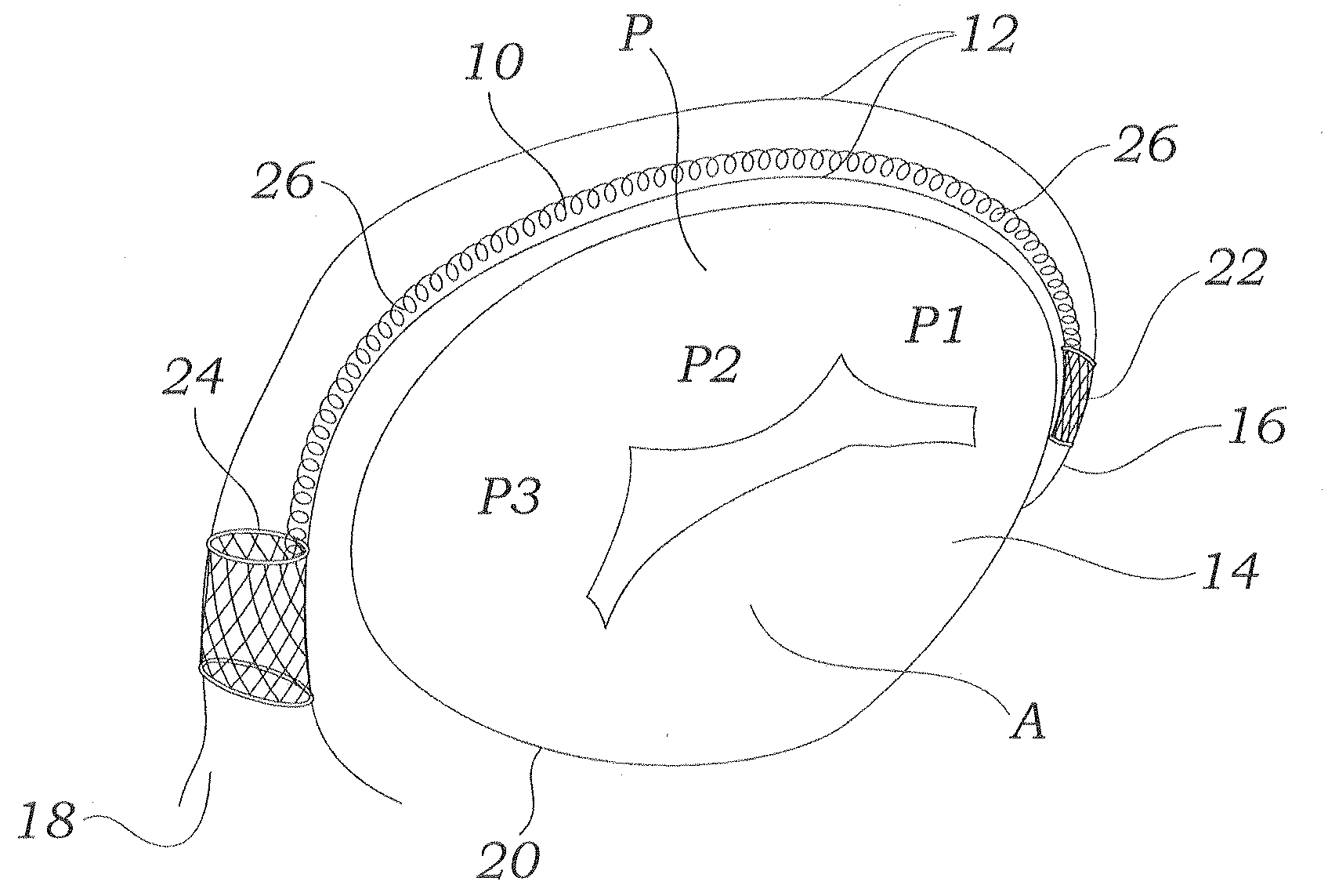
[0032]FIG. 1 depicts an implant 10 of the current invention deployed in the coronary sinus 12 of a mitral valve 14. From this view, it can be seen that the coronary sinus 12 extends around a posterior region of the mitral valve 14. The coronary sinus 12 is a relatively large vessel that receives venous drainage from the heart muscle. Blood flows through the coronary sinus 12 from a relatively narrow distal portion 16 and empties into the right atrium through a relatively wide coronary ostium 18. The mitral valve 14 generally includes an anterior leaflet A and a posterior leaflet P. The posterior leaflet P is formed with three scallops P1, P2, and P3. A mitral annulus 20 is a portion of tissue surrounding the mitral valve 14 to which the valve leaflets A, P attach. The coronary sinus 12 passes around the mitral valve 14 generally parallel to the mitral annulus 20 adjacent the posterior leaflet P.

[0033]As used herein, the term coronary sinus 12 is used as a generic term that describes...


PUM


Abstract

An apparatus for treating a mitral valve, comprising an elongate member having a spiral shape, the elongate member having a proximal end portion and a distal end portion, an expandable proximal anchor joined to the proximal end portion of the elongate body, and an expandable distal anchor joined to the distal end portion of the elongate body. The elongate member is configured to adjust from an elongated state to a shortened state after delivery at least partially into a coronary sinus for reshaping a mitral annulus.

Description

CROSS REFERENCE TO RELATED APPLICATIONS[0001]The present application claims priority to U.S. Provisional Patent Application No. 60 / 772,984, filed on Feb. 9, 2006, entitled “Coiled Implant for Mitral Valve Repair,” the disclosure of which is incorporated by reference herein in its entirety.FIELD OF THE INVENTION[0002]The present invention relates to a medical implant, and more particularly to a medical implant for treating a mitral valve.BACKGROUND[0003]Heart valve regurgitation, or leakage from the outflow to the inflow side of a heart valve, is a condition that occurs when a heart valve fails to close properly. Regurgitation through the mitral valve is typically caused by changes in the geometric configurations of the left ventricle, papillary muscles and mitral annulus. Similarly, regurgitation through the tricuspid valve is typically caused by changes in the geometric configurations of the right ventricle, papillary muscles and tricuspid annulus. These geometric alterations resul...

Claims


Application Information

Patent Timeline
IPC IPC(8): A61F2/24
CPCA61B2017/00243A61F2250/0004A61F2/2451
Inventor SOLEM, JAN OTTOKALAM, FAISALPOPP, MICHAELZHANG, XIANGYANG
Owner EDWARDS LIFESCIENCES CORP
Why Eureka
Try Eureka