Eureka AIR delivers breakthrough ideas for toughest innovation challenges, trusted by R&D personnel around the world.

Filter element

Active Publication Date: 2007-08-16
PARKER HANNIFIN LTD HEMEL HEMPSTEAD
View PDF6 Cites 0 Cited by
  • Summary
  • Abstract
  • Description
  • Claims
  • Application Information

AI Technical Summary

Benefits of technology

[0003] Filtration of gas in a compressed gas system is generally required so that the gas is sufficiently clean for a subsequent application or to minimise adverse effects of impurities on components of the system. For example, removal of compressor oil can be required to minimise chemical contamination and accumulation on valves which might lead to malfunction of the valves.

Problems solved by technology

This can increase the resistence to flow of gas through the filter element, and therefore also an increase in pressure drop across the filter element.
Furthermore, gas flowing through or near a saturated part of the drainage layer can draw droplets of liquid from the drainage layer into the gas flow, thereby re-contaminating the gas as it exits the filter element.
It can therefore be seen that significant accumulation of liquid in a wet band can reduce the operating efficiency of the filter element.
When the operating efficiency is significantly reduced, the filter element in the filter assembly must be replaced, giving rise to expense and possibly also a requirement for the system in which the assembly is used to be shut down.

Method used


Image

  • Filter element
  • Filter element
  • Filter element

Examples


Embodiment Construction

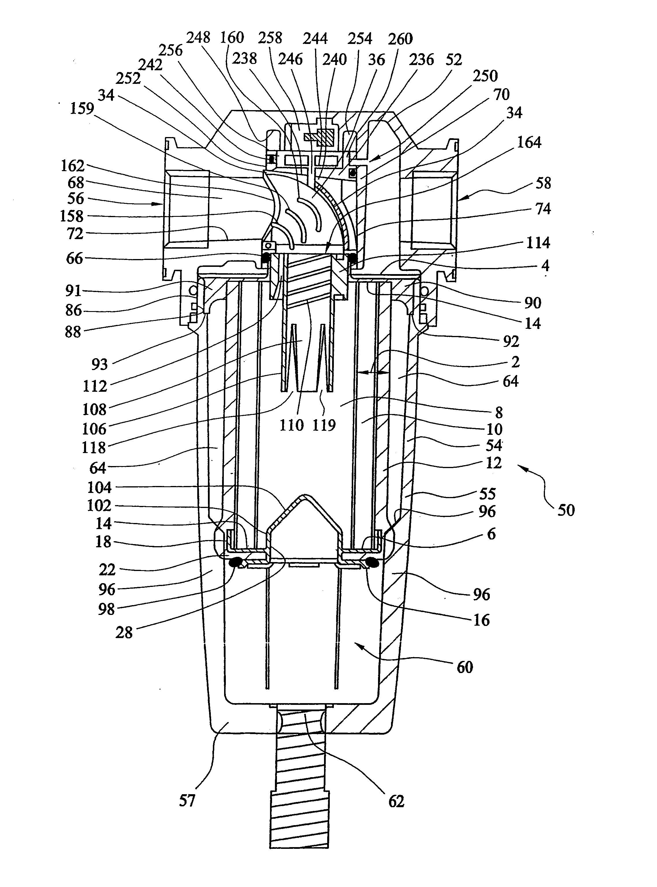
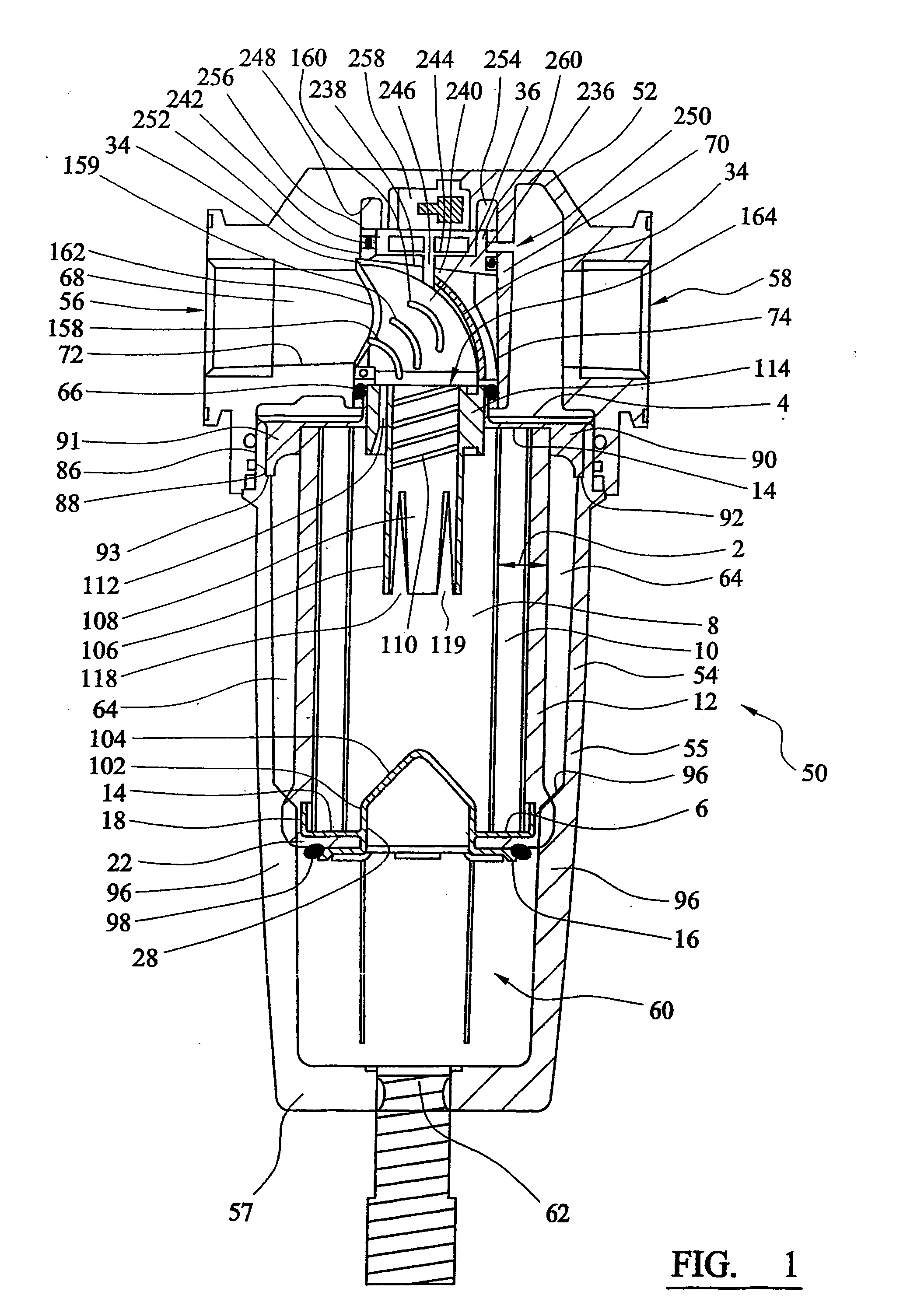
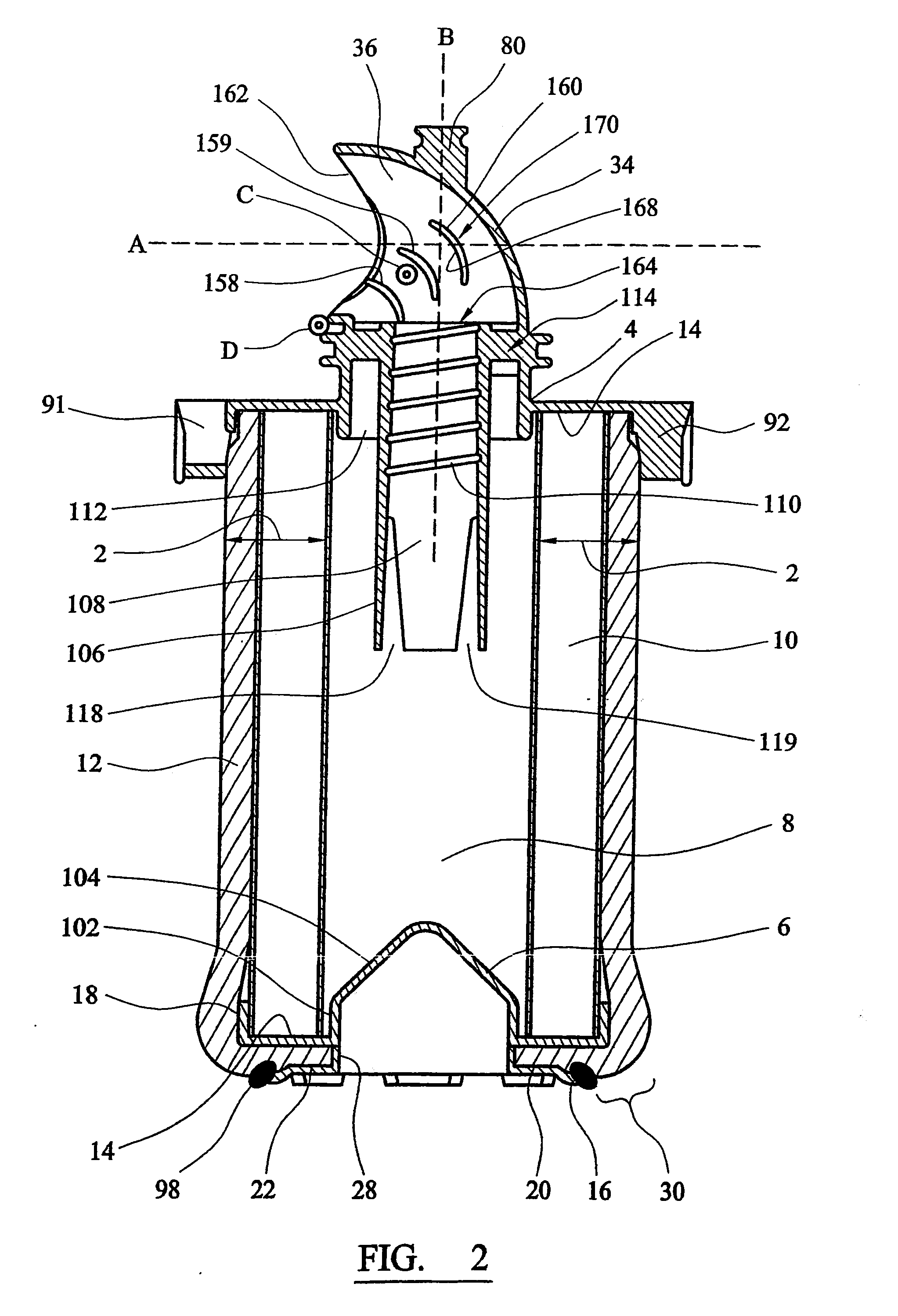
[0112] Referring to the drawings, FIG. 2 shows a filter element which comprises a cylindrical wall section 2 formed from a filter medium, and top and bottom end caps 4 and 6.

[0113] The wall section 2 defines a hollow space 8 within it. The filter medium of the wall 2 comprises a cylindrical filtration layer 10 and a cylindrical anti-reentrainment layer or drainage layer 12 which fits snugly around the filtration layer on the outside of the filter element.

[0114] The top end cap 4 contains a flow conduit 34 which defines a flow path 36 for gas which is to be filtered. The flow conduit 34 has a port 80 in it for connection to a gauge for measuring the differential pressure across the filter element. When the filter element is located within a housing (described in more detail below) the port 80 can be received in a downwardly facing socket in the housing head, forming a seal by compression of an O-ring between the external surface of the port and the internal surface of the socket.

[...


PUM

PropertyMeasurementUnit
Lengthaaaaaaaaaa
Angleaaaaaaaaaa
Lengthaaaaaaaaaa

Abstract

A hollow filter element for removing material that is entrained in a gas stream. The filter element comprises a wall of a filtration medium which defines a hollow space so that a gas stream can flow from the space through the wall in order to be filtered. The wall comprises a filtration layer, and a drainage layer located outside the filtration layer in which liquid separated from the gas stream can collect. The filter element further comprises first and second end caps at opposite ends of the space, the first end cap including an inlet for a gas stream to be supplied to the space. The drainage layer extends from the wall over at least a part of the external surface of second end cap, over the face thereof which faces away from the first end cap.

Description

CROSS REFERENCE TO RELATED APPLICATIONS [0001] This application is continuation of copending International Application No. PCT / GB05 / 002915 filed Jul. 26, 2005, which designated the United States, the disclosure of which is incorporated herein by reference, and which claims priority to Great Britain Patent Application 0417455.3, filed Aug. 5, 2004. BACKGROUND OF THE INVENTION [0002] The present invention relates to a filter element for removing material that is entrained in a gas stream such as liquid in an aerosol form, and to a filter assembly in which the filter element is used. SUMMARY OF THE INVENTION [0003] Filtration of gas in a compressed gas system is generally required so that the gas is sufficiently clean for a subsequent application or to minimise adverse effects of impurities on components of the system. For example, removal of compressor oil can be required to minimise chemical contamination and accumulation on valves which might lead to malfunction of the valves. [0004...

Claims


Application Information

Patent Timeline
IPC IPC(8): B01D46/00B01D17/04B01D46/24
CPCB01D17/045B01D46/2414B01D46/0045B01D46/0031
Inventor PEARSON, JOHNBITTLE, THOMAS STEPHENTROWSDALE, RAYMOND FRANCISLANE, BRIAN
Owner PARKER HANNIFIN LTD HEMEL HEMPSTEAD
Why Eureka
Eureka Blog
Learn More